• Photonics Research
  • Vol. 11, Issue 6, 1015 (2023)
J. P. Trevino1、2, V. Coello3、*, A. Jaimes-Nájera1, C. E. Garcia-Ortiz1, S. Chávez-Cerda4, and J. E. Gómez-Correa4
Author Affiliations
  • 1Tecnológico de Monterrey, School of Engineering and Sciences, Monterrey NL 64849, Mexico
  • 2Universidad Politécnica de Puebla, Cuanalá Puebla 72640, Mexico
  • 3Centro de Investigación Científica y de Educación Superior de Ensenada, Unidad Monterrey, Apodaca NL 66629, Mexico
  • 4Instituto Nacional de Astrofísica, Óptica y Electrónica, Coordinación de Óptica, Tonantzintla Puebla 72840, Mexico
  • show less
    DOI: 10.1364/PRJ.482323 Cite this Article Set citation alerts
    J. P. Trevino, V. Coello, A. Jaimes-Nájera, C. E. Garcia-Ortiz, S. Chávez-Cerda, J. E. Gómez-Correa. Direct observation of longitudinal aberrated wavefields[J]. Photonics Research, 2023, 11(6): 1015 Copy Citation Text show less

    Abstract

    Rather than focusing on a focal spot, aberrated wavefields spread out over a region. As a wave phenomenon, optical aberrations are analyzed in terms of waves propagating in the 3D space. In this work, we report the observation of 2D longitudinal aberrated wavefields. This observation can be visualized by mapping the intensity distributions of surface plasmon polaritons (SPPs) that propagate on a metal/air interface using leakage radiation microscopy. The orientation of the SPP beam is tweaked by tilting and translating the system to mimic aberrated beams, presenting known Seidel terms: defocus, spherical, coma, and tilt aberration. This approach allows the examination of the longitudinal evolution of aberrated beams in a visual and rapid manner, in contrast to more complicated post-processing reconstructions.

    1. INTRODUCTION

    An ideal optical imaging system will produce point images of point objects. From the geometrical optics, it is well known that the light rays emerging from the exit pupil converge at the image point that is located at the focal plane. In the case of wave optics, the wavefronts converge at the denominated focal spot. In both models, any deviations from the ideal mathematical behavior are referred to as optical aberrations. Optical aberrations are phenomenologically well described by either the geometrical or the wavefront aberration theories [1]. Geometrical ray tracing is performed considering radially symmetric systems. Due to this symmetry, the ray tracing is typically shown along the longitudinal axes; i.e., at the tangential and sagittal planes. In addition, the propagation of wavefronts (from exit pupil to focal plane) is also usually represented at those same optical planes. However, in both geometrical and wave optics, it is at the transverse planes where the quantitative analysis is mostly carried out [2], which is shown in Fig. 1. In general, a direct experimental observation of the longitudinal field distribution of a beam is rather complicated by means of conventional imaging systems. For this reason, most of the efforts in this direction have been nontrivial and require multiple cross-sectional images to reconstruct the longitudinal intensity distribution [39]. Access to the longitudinal field is of upmost importance in studies such as those on highly focused beams where, under certain conditions, a longitudinal electric field with more energy than the transverse one can be produced [10]. In this context, access to the phase field also represents a challenge. It can be done, to a certain extent, by interferometric techniques; however, it requires adding more complexity to the experimental setup [9]. Recently, it has been shown how information encoding complex amplitude and phase from a Gaussian beam propagating in a 3D space can be transferred to 2D propagating fields by coupling the beam to surface plasmon polaritons (SPPs) [11]. Furthermore, SPP shaping can be achieved by adjusting the characteristics of the incident light such as the phase [12] and the incident angle [13,14] while using a fixed excitation structure. Other investigations have applied diffractive-type effects to focus SPP-coupled fields, and shallow-gravity waves by means of the so-called diffractive focusing properties of the diffracting fields [15,16]. These advantages were a motivation for this work and led us to obtain what we believe, to the best of our knowledge, is the first direct observations of transverse aberrated fields in a longitudinal plane. We demonstrated the experimental possibility of the real-time mapping of the longitudinal field amplitude distribution along the direction of propagation in the longitudinal plane of selected aberrated optical fields throughout the whole propagation path. The images were obtained using leakage radiation microscopy (LRM), which is a technique that features the inverted Kretschmann configuration for both SPP excitation and detection mechanisms [17]; in other words, it is a technique that consists of imaging the leakage radiation, which decouples into freely propagating light that carries the intensity and phase information of the SPP mode. The on-demand induction of the selected Seidel aberrations to an SPP was introduced by minor modifications to the incident beam in the LRM system; namely, rotations and translations. Although the experiment shows specific aberrations, we expect that this same effect will be observed in arbitrary systems, thus providing what we believe is a novel way to measure aberrations as well as structured beams. Similar experiments [18] have been performed where a similar setup (SPP excited by a Kretschmann configuration) is exploited to accurately measure Zernike aberration coefficients and thus function as a wavefront sensor. These experiments are different from our experiment, which displays the aberrated field as it propagates. Our findings can be applied to microscope calibration and, in a general sense, the results contribute to the proper characterization of the evolution of rays and wavefronts throughout a whole propagation path.

    3D representation of a beam propagation. The beam is aberrated with coma; the main planes where the analyses take place are indicated with blue squares parallel to each plane.

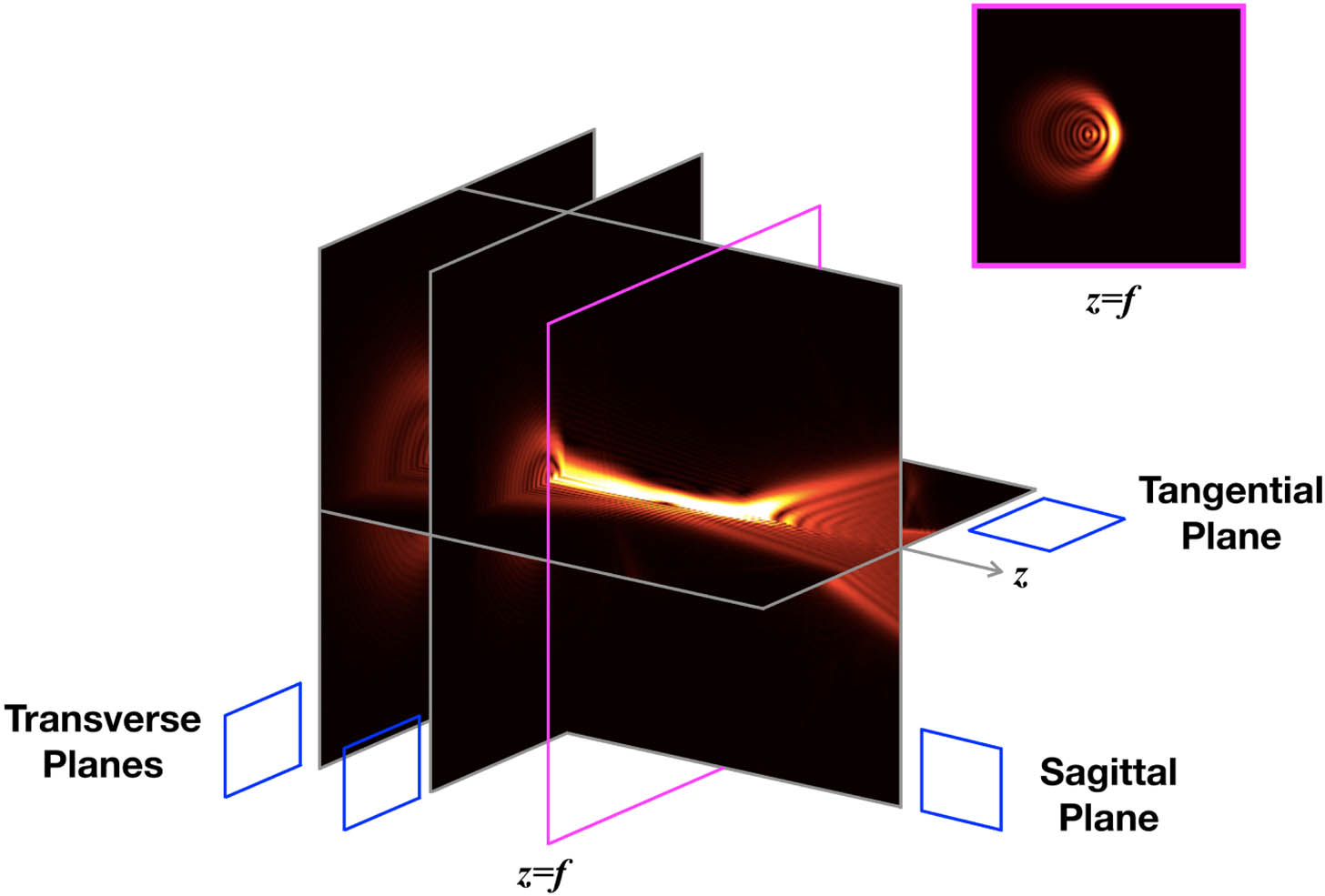
    Figure 1.3D representation of a beam propagation. The beam is aberrated with coma; the main planes where the analyses take place are indicated with blue squares parallel to each plane.

    2. MINIMAL THEORY OF ABERRATIONS

    In this section we briefly review concepts related to phase aberrations.

    Given a complex wavefield at the exit pupil of an optical system represented by P(ρ,ϕ) with ρ, ϕ the polar coordinates at the pupil’s plane, the Fresnel integral provides a direct means to calculate the field distribution uz at different propagation distances z from a monochromatic field of wavelength λ [1,2,19] by uz(r,θ)=Cππ0P(ρ,ϕ)eiπλzρ2ei2πλzrρcos(ϕθ)ρdρdϕ,where C is a constant factor and r, θ are the polar coordinates of the observation plane. The complex pupil function that fully characterizes the optical system is P(ρ,ϕ)=T(ρ,ϕ)ei2πλW(ρ,ϕ)eiπλzρ2,which contains both transmittance T(ρ,ϕ) and phase information (2π/λ)W(ρ,ϕ). The exit pupil of an imaging system is ideally a converging sphere, and any departure from such is called an aberration. The wave aberration W(ρ,ϕ) is usually expanded in orthogonal modes [20,21]. However, for geometrical reasons, the aberration function is often limited to the Seidel terms [20] as W(ρ,ϕ)=Atρcosϕ+Adρ2+Aaρ2cos2ϕ+Acρ3cosϕ+Asρ4,where the aberration coefficients Ai can take either positive or negative values and represent peak aberration values. The subscripts of the coefficients represent (t) tilt, (d) defocus, (a) astigmatism, (c) coma, and (s) spherical aberration [22].

    For longitudinal profiles, we take the angle ϕ=0, so that the wave aberration becomes [20,21] W(ρ,ϕ)=Atρ+Adρ2+Aaρ2+Acρ3+Asρ4.

    Each term of this equation is plotted in Fig. 2. From Eq. (4), it is readily observed that defocus and astigmatism become indistinguishable on the xy plane, so astigmatism is dropped in the experiments since we are dealing with longitudinal planes. In the following sections we will describe how these phases are obtained by introducing simple modifications to a widely known SPP experimental array.

    Each one of the Seidel terms for wave aberrations is plotted. The piston aberration is just a wave delay, while the tilt has a linear variation. The slope is proportional to the tilt angle of the incident beam. Defocus is a quadratic function and coma is cubic.

    Figure 2.Each one of the Seidel terms for wave aberrations is plotted. The piston aberration is just a wave delay, while the tilt has a linear variation. The slope is proportional to the tilt angle of the incident beam. Defocus is a quadratic function and coma is cubic.

    3. EXPERIMENTAL TECHNIQUES

    The experimental setup used for this research has been described in detail elsewhere [23]. To engineer specific Seidel aberrations, minor deviations of the standard LRM illumination conditions were introduced [14]. The illuminated system in its original configuration is depicted in Fig. 3(a), where the wavefronts are conveniently (and correctly) indicated. The beam may be tilted as shown in Fig. 3(b), and its waist displaced as shown in 3D in Fig. 3(c). Here, a single ridge on top of a gold film was used as the mechanism for the local light-SPP coupling [24] (Fig. 4). SPP propagation can be described as a continuous function and therefore the image resolution is only limited by the collecting system or imaging CCD. Thus, the SPP fields were generated by directing the laser beam onto the gold ridge with a 10× microscope objective (NA=0.25) to generate plasmonic beams with low divergence. A 40× microscope objective (NA=0.65) was used to generate beams with a larger divergence. The scattered light generates two symmetrical SPP fields propagating in the direction perpendicular to the ridge. Both fields have almost identical properties, and only one of them is visualized for this study. The whole mechanism serves, in our case, as a system for 2D projection and direct visualization of the induced wavefront aberrations. To generate the SPP engineered field profiles, four specific excitation illumination conditions were used in the experiment. In general, our sample consists of a 170 μm thick silica substrate covered by thermal evaporation with a 70 nm gold thin film. Electron beam lithography (EBL) was used to fabricate a gold ridge of 70 nm thick and 200 nm wide. The geometric parameters of the sample are optimized for the working wavelength (750 nm, p-pol) in accordance with previous reports [11,14].

    How to adjust the system. The exit pupil plane is in yellow. The position of the sample relative to the Gaussian beam: (a) with the initial alignment to get an unaberrated field and with a displacement to get a defocused field and (b) with a tilt and a displacement to get tilted and comatic aberrations. This figure illustrates how there are regions of the wavefront arriving at the sample ahead of others, thus producing the desired Seidel aberrations. (c) Moving the beam is equivalent to moving the sample since the wavefront is incident on the plane with the same phase shifts.

    Figure 3.How to adjust the system. The exit pupil plane is in yellow. The position of the sample relative to the Gaussian beam: (a) with the initial alignment to get an unaberrated field and with a displacement to get a defocused field and (b) with a tilt and a displacement to get tilted and comatic aberrations. This figure illustrates how there are regions of the wavefront arriving at the sample ahead of others, thus producing the desired Seidel aberrations. (c) Moving the beam is equivalent to moving the sample since the wavefront is incident on the plane with the same phase shifts.

    Image of an LRM system. The angle α and the distance from the beam waist to the golden ridge are the parameters that determine the Seidel aberration. A waist shift will produce a defocus because the beam will arrive at the ridge at a point where the front is converging, while changing an angle α produces a tilt if the beam waist is at the ridge; otherwise, a coma is produced.

    Figure 4.Image of an LRM system. The angle α and the distance from the beam waist to the golden ridge are the parameters that determine the Seidel aberration. A waist shift will produce a defocus because the beam will arrive at the ridge at a point where the front is converging, while changing an angle α produces a tilt if the beam waist is at the ridge; otherwise, a coma is produced.

    4. RESULTS

    In this section, we present the LRM results and the corresponding numerical results of the generated longitudinal intensity profiles. The numerical calculations have been carried out by means of the beam propagation method (BPM) [25]. Our simulations include a decaying factor due to the vanishing nature of SPPs, thus allowing a more realistic description of the physics. Note that the longitudinal field that we are probing is the longitudinal electric field polarized in the direction of propagation of the incident beam. From Fourier analysis [19], it is possible to show that the longitudinal component of the incident beam couples to the transverse component of the SPP mode (normal to the interface), and the transverse component of the incident beam couples to the longitudinal component of the SPP. The ratio between the magnitudes of the transverse and longitudinal electric-field components for SPPs is obtained from the boundary conditions and conservation of the wavevector. Near the infrared region of the spectrum, the normal component of the field is at least five times larger than the longitudinal component. Therefore, the main contribution to the SPP field comes from the longitudinal components of the incident Gaussian beam, which can be probed through the intensity distribution observed from the leakage radiation.

    A. Aberration-Free Case

    First, we will consider the aberration-free case as the one in which the beam waist (or beam focus) directly impinges on the ridge. The LRM system, being a far-field detection technique, is diffraction limited. Nevertheless, since we used a large exit pupil-to-spot ratio and assume that the aberrations of the objective lens are minimal (i.e., they are well-corrected), the field that arrives at the sample is not far from its original Gaussian shape [Fig. 5(a)]. We shall emphasize that even if all the potential defects in the image formation system would be eliminated, the ultimate sharpness of the image is still diffraction limited. Thus, the typical intensity distribution of an SPP Gaussian beam [11] was observed from the recorded LRM image [Fig. 5(b)]. Such a plasmonic beam inherits all the well-known Gaussian beam properties and represents a direct far-field visualization of its longitudinal amplitude distribution. Figures 5(c) and 5(d) show the numerical simulations of the 3D beam propagation.

    Aberration-free beam. (a) Incident Gaussian light beam focused with the 10× objective. (b) LRM image of the intensity distribution of SPP propagating from left to right. (c) and (d) Corresponding numerical simulations of the 3D beam propagation.

    Figure 5.Aberration-free beam. (a) Incident Gaussian light beam focused with the 10× objective. (b) LRM image of the intensity distribution of SPP propagating from left to right. (c) and (d) Corresponding numerical simulations of the 3D beam propagation.

    Tilting the incident beam. (a) Incident light beam focused with the 40× objective. (b) LRM image of the intensity distribution of SPP propagating from left to right. (c) and (d) Corresponding numerical simulations of the 3D beam propagation.

    Figure 6.Tilting the incident beam. (a) Incident light beam focused with the 40× objective. (b) LRM image of the intensity distribution of SPP propagating from left to right. (c) and (d) Corresponding numerical simulations of the 3D beam propagation.

    B. Tilt Aberration

    We will carry on with the tilt aberration case that was achieved using the LRM setup configured to allow oblique illumination. In general, this configuration allows control of the angle at which the light leaves the focusing objective, and thereby controls the incidence angle of the beam relative to the perpendicular direction of the sample surface. The entire procedure has been described in detail elsewhere [14]. Note that in that case the angle of inclination is in a plane perpendicular to the one described in this report. We would like to emphasize that by controlling the incident angle, the generated SPP wave vector direction can be precisely modulated in a wide optical spectral region [13]. When the incident light forms an angle α along the longitudinal direction of the ridge (i.e., with respect to the xy plane, but slightly decentered with respect to it, as shown in Fig. 4), the tilt aberration is reproduced. This occurs when the wavefront, from the point object, is tilted or decentered with respect to the optical axis of the optical system. The resulting LRM map is qualitatively similar to the aberration-free case and exhibits the tilted Gaussian beam propagation. The experimental results are shown in Figs. 6(a) and 6(b) and the numerical simulation is shown in Figs. 6(c) and 6(d). The corresponding Seidel term in Eq. (3) is Atρcosϕ and its peak value is proportional to the tilting angle α. This may be observed from Fig. 4. The tilting angle is proportional to the slope of the graph, as shown in Figs. 2 and 3.

    C. Defocus Aberration

    As mentioned earlier, a typical LRM illumination configuration consists of a beam focused on the structure under study so that the waist position of the excited SPP Gaussian beam coincides with its excitation point. For the case of a defocus aberration, the optical excitation of SPP is achieved by moving (mechanically) the focal plane of the objective behind the excitation ridge. In other words, the SPP beam is excited with the defocused (converging) Gaussian laser beam. The excited SPP mode again preserves characteristic information of the incident beam and therefore reproduces the longitudinal field of the defocused propagating beam; the experimental observation is shown in Fig. 7(b) and the numerical simulation is in Fig. 7(d). Regarding phase information, it can be readily noted that the wavefront arriving at the sample is converging. The on-axis part of the beam is behind the rest of the beam and the delay increases with ρ2. Figure 3(a) is a visual aid for this situation. The wavefront of the Gaussian beam is approximately parabolic (converging) at this point, so it corresponds to the second-order term (i.e., defocus) in Eq. (3). Its peak value is proportional to the mechanical shifting distance.

    Defocused beam. (a) Incident light beam defocused with the 40× objective. (b) LRM image of the intensity distribution of SPP propagating from left to right. (c) and (d) Corresponding numerical simulations of the 3D beam propagation.

    Figure 7.Defocused beam. (a) Incident light beam defocused with the 40× objective. (b) LRM image of the intensity distribution of SPP propagating from left to right. (c) and (d) Corresponding numerical simulations of the 3D beam propagation.

    D. Coma Aberration

    A two-step process was used to introduce the coma aberration. First, using the same procedure as the previous case, a defocused illumination beam was generated. To complete the process, an oblique illumination was added that was generated in the same way as for the case of tilt aberration. As described in the process, note that to produce tilt and defocus aberrations rotations and translations are encoded directly into the W(ρ,ϕ) and are in one-to-one correspondence with the mechanical operations (i.e., rotations and translations) to the illumination system. In Fig. 3(b), the result of shifting and tilting the illumination system with respect to the ridge produces wavefronts with a coma-like aberration. Figure 8(b) shows the recorded SPP mode that notably reproduces the longitudinal field of a comatic aberration of Fig. 8(d). In this case, the coma aberration term is the product of the phase terms of first and second orders so that successive mechanical operations correspond to a product of the wavefront terms.

    Coma-like beam. (a) Incident light beam defocused with the 40× objective. (b) LRM image of the intensity distribution of SPP propagating from left to right. (c) and (d) Corresponding numerical simulations of the 3D beam propagation.

    Figure 8.Coma-like beam. (a) Incident light beam defocused with the 40× objective. (b) LRM image of the intensity distribution of SPP propagating from left to right. (c) and (d) Corresponding numerical simulations of the 3D beam propagation.

    E. Astigmatism and Spherical Aberration

    Astigmatic aberration is produced by the presence of different curvature radii at two different axes. This causes light to produce focal lines at two different planes for each curvature, rather than a single focal spot. The cases presented here consider the propagation plane at ϕ=0 (Section 2) so that the astigmatism term becomes identical to the defocus term, which can be observed in Eq. (3). Spherical aberration features a fourth-order term and, since Gaussian beams have a parabolic phase, it is not possible to mimic the spherical term by only geometrical transformations.

    5. DISCUSSION

    The field at the sample plane comes from a diffraction-limited system. When the pupil was large enough to let the Gaussian beam with minimal perturbation, a fundamental beam was observed as in Ref. [11] and in the Seidel tilt term shown in this work. However, other fields shown in this paper feature a notorious diffraction effect because the beam has been expanded before the pupil. This information is encoded in the T(ρ,ϕ) factor of Eq. (2). A wave aberration occurs when certain regions of the incident wavefront are actually ahead of the ideal converging phase, while other elements are behind it. In Fig. 3, the necessary tweaking to obtain the corresponding wavefronts is shown. If the LRM experimental arrangement is perfectly aligned, the beam waist coincides with the pupil plane and there is no relative phase difference and thus no aberration, so an SPP that focuses at the focal spot is observed. If the system is rotated at the waist position so that half of the beam is ahead of the phase while the other half is behind it, then we will observe a tilted version of the SPP that corresponds to the tilt aberration. The SPP would converge to a single focal spot but not at the original longitudinal axis. The experiment carried out here was a nonexpanded beam, so we observed the fundamental (undiffracted) Gaussian beam. A defocused SPP was obtained by shifting the LRM system away from or toward the sample, with no tilt. As a result, the incident beam is either converging (if the system is pushed closer to the sample) or diverging (if the system is pulled away). Tilts and translations are encoded directly in the W(ρ,ϕ) factor and are in one-to-one correspondence with the imaging systems. Finally, by applying both a translation and a rotation, as shown in Fig. 8(c), a comatic field is generated. The remarkable phase-copying effect of the SPP allowed the observations presented in this paper.

    6. CONCLUSION

    In conclusion, since the properties of a Gaussian beam propagating in 3D space were inherited to an SPP field by a light-coupling mechanism, it was possible to obtain a direct visualization of the longitudinal amplitude distribution of an aberrated wavefront field using LRM techniques. To the best of our knowledge, there are no reports on this 2D projection of the presented specific Seidel aberration terms. Since the SPP carried phase information from the incident excitation illumination, the propagation of the SPP was identical to the longitudinal plane of the Seidel aberrated fields. Our results might be understood as a generalization of Refs. [15,16] since aberrated fields constitute the most general type of wavefields. The key lies in the mathematical approximations that led to the Schrödinger-like equations, and the well-known generalized Gaussian solutions corresponding to particular boundary conditions. We believe these observations open avenues toward theories and applications for structured plasmonic beams.

    Acknowledgment

    Acknowledgment. The authors would like to thank E. Pisano for valuable help in the laboratory.

    References

    [1] M. Born, E. Wolf. Principles of Optics: Electromagnetic Theory of Propagation, Interference and Diffraction of Light(1999).

    [2] V. N. Mahajan. Optical Imaging and Aberrations: Part I. Ray Geometrical Optics(1998).

    [3] M. Kovalev, I. Gritsenko, N. Stsepuro, P. Nosov, G. Krasin, S. Kudryashov. Reconstructing the spatial parameters of a laser beam using the transport-of-intensity equation. Sensors, 22, 1765(2022).

    [4] A. Bouhelier, M. Beversluis, A. Hartschuh, L. Novotny. Near-field second-harmonic generation induced by local field enhancement. Phys. Rev. Lett., 90, 013903(2003).

    [5] G. Kihara Rurimo, M. Schardt, S. Quabis, S. Malzer, C. Dotzler, A. Winkler, G. Leuchs, G. H. Döhler, D. Driscoll, M. Hanson, A. C. Gossard, S. F. Pereira. Using a quantum well heterostructure to study the longitudinal and transverse electric field components of a strongly focused laser beam. J. Appl. Phys., 100, 023112(2006).

    [6] L. Novotny, M. R. Beversluis, K. S. Youngworth, T. G. Brown. Longitudinal field modes probed by single molecules. Phys. Rev. Lett., 86, 5251-5254(2001).

    [7] B. Hao, J. Leger. Experimental measurement of longitudinal component in the vicinity of focused radially polarized beam. Opt. Express, 15, 3550-3556(2007).

    [8] Y. Kozawa, S. Sato. Observation of the longitudinal field of a focused laser beam by second-harmonic generation. J. Opt. Soc. Am. B, 25, 175-179(2008).

    [9] D. Maluenda, M. Aviñoá, K. Ahmadi, R. Martínez-Herrero, A. Carnicer. Experimental estimation of the longitudinal component of a highly focused electromagnetic field. Sci. Rep., 11, 17992(2021).

    [10] K. A. Forbes, D. Green, G. A. Jones. Relevance of longitudinal fields of paraxial optical vortices. J. Opt., 23, 075401(2021).

    [11] C. E. Garcia-Ortiz, E. Pisano, V. Coello. Description and characterization of plasmonic Gaussian beams. J. Opt., 19, 085001(2017).

    [12] C.-F. Kuo, S.-C. Chu. Launching of surface plasmon polaritons with tunable directions and intensity ratios by phase control of dual fundamental Gaussian beams. Opt. Express, 25, 10456-10463(2017).

    [13] P. Qiu, D. Zhang, M. Jing, T. Lu, B. Yu, Q. Zhan, S. Zhuang. Dynamic tailoring of surface plasmon polaritons through incident angle modulation. Opt. Express, 26, 9772-9783(2018).

    [14] E. Pisano, C. E. Garcia-Ortiz, F. Armenta-Monzon, M. Garcia-Mendez, V. Coello. Efficient and directional excitation of surface plasmon polaritons by oblique incidence on metallic ridges. Plasmonics, 13, 1935-1940(2018).

    [15] D. Weisman, S. Fu, M. Gonçalves, L. Shemer, J. Zhou, W. P. Schleich, A. Arie. Diffractive focusing of waves in time and in space. Phys. Rev. Lett., 118, 154301(2017).

    [16] D. Weisman, C. M. Carmesin, G. G. Rozenman, M. A. Efremov, L. Shemer, W. P. Schleich, A. Arie. Diffractive guiding of waves by a periodic array of slits. Phys. Rev. Lett., 127, 014303(2021).

    [17] A. Drezet, A. Hohenau, D. Koller, A. Stepanov, H. Ditlbacher, B. Steinberger, F. Aussenegg, A. Leitner, J. Krenn. Leakage radiation microscopy of surface plasmon polaritons. Mater. Sci. Eng. B, 149, 220-229(2008).

    [18] B. Vohnsen, D. Valente. Surface-plasmon-based wavefront sensing. Optica, 2, 1024-1027(2015).

    [19] J. W. Goodman. Introduction to Fourier Optics(2005).

    [20] V. N. Mahajan. Zernike polynomials and optical aberrations. Appl. Opt., 6, 8060-8062(1995).

    [21] J. P. Treviño, J. E. Gómez-Correa, D. R. Iskander, S. Chávez-Cerda. Zernike vs. Bessel circular functions in visual optics. Ophthal. Physiol. Opt., 33, 394-402(2013).

    [22] V. N. Mahajan. Strehl ratio for primary aberrations: some analytical results for circular and annular pupils. J. Opt. Soc. Am., 72, 1258-1266(1982).

    [23] C. Garcia, V. Coello, Z. Han, I. P. Radko, S. I. Bozhevolnyi. Partial loss compensation in dielectric-loaded plasmonic waveguides at near infrared wavelengths. Opt. Express, 20, 7771-7776(2012).

    [24] I. P. Radko, S. I. Bozhevolnyi, G. Brucoli, L. Martín-Moreno, F. J. García-Vidal, A. Boltasseva. Efficiency of local surface plasmon polariton excitation on ridges. Phys. Rev. B, 78, 115115(2008).

    [25] M. D. Feit, J. A. Fleck. Light propagation in graded-index optical fibers. Appl. Opt., 17, 3990-3998(1978).

    J. P. Trevino, V. Coello, A. Jaimes-Nájera, C. E. Garcia-Ortiz, S. Chávez-Cerda, J. E. Gómez-Correa. Direct observation of longitudinal aberrated wavefields[J]. Photonics Research, 2023, 11(6): 1015
    Download Citation