• Chinese Optics Letters
  • Vol. 18, Issue 8, 080002 (2020)
Qi Guo1、2、*, Tian Liu1、2, Xiaoqian Wang3、**, Zhigang Zheng3, Aleksey Kudreyko4, Huijie Zhao1、2, V. Chigrinov5、6、7, and Hoi-Sing Kwok6
Author Affiliations
  • 1School of Instrumentation and Optoelectronic Engineering, Beihang University, Beijing 100191, China
  • 2Beihang University Qingdao Research Institute, Qingdao 266101, China
  • 3Physics Department, East China University of Science and Technology, Shanghai 200237, China
  • 4Department of Medical Physics and Informatics, Bashkir State Medical University, Ufa 450008, Russia
  • 5School of Physics and Optoelectronic Engineering, Foshan University, Foshan 528000, China
  • 6State Key Laboratory on Advanced Displays and Optoelectronics Technologies, The Hong Kong University of Science and Technology, Hong Kong 999077, China
  • 7Department of Theoretical Physics, Moscow Region State University, Mytishi 141014, Russia
  • show less
    DOI: 10.3788/COL202018.080002 Cite this Article Set citation alerts
    Qi Guo, Tian Liu, Xiaoqian Wang, Zhigang Zheng, Aleksey Kudreyko, Huijie Zhao, V. Chigrinov, Hoi-Sing Kwok. Ferroelectric liquid crystals for fast switchable circular Dammann grating [Invited][J]. Chinese Optics Letters, 2020, 18(8): 080002 Copy Citation Text show less

    Abstract

    Diffractive optical elements attract a considerable amount of attention, mainly due to their potential applications in imaging coding, optical sensing, etc. Application of ferroelectric liquid crystals (FLCs) with photo-alignment technology in diffractive optical elements results in a high efficiency and a fast response time. In this study we demonstrate a circular Dammann grating (CDG) with a diffraction efficiency of 84.5%. The achieved response time of 64 μs is approximately two orders of magnitude faster than the existing response time of nematic liquid crystal devices. By applying a low electric field (V = 6 V) to the FLC CDG, it is switched between the eight-order diffractive state and the transmissive diffraction-free state.

    Diffractive optical elements with attractive characteristics, i.e., excellent performance and compact size, are becoming increasingly important to a wide range of optical system technologies[17]. Thus, an effective method of design and fabrication of fast-switchable and highly efficient diffractive optical elements is in high demand. Circular Dammann gratings (CDGs), which generate a concentric and uniform energy distribution, have many applications in image coding[8,9], beam shaping[10], vortex manipulation[11,12], and precise measurements[13,14]. Much effort has been expended to enhance the efficiency and the uniformity of CDGs by profile optimization[1517]. However, realization of tunable CDGs has been accomplished only in recent years. Electro-optical properties of nematic liquid crystals with a patterned alignment and sensitivity to the electric field make it possible to fabricate tunable CDGs, albeit with a relatively slow response time[1820].

    In terms of response time, ferroelectric liquid crystals (FLCs) are two orders of magnitude faster than the existing nematic liquid crystals[21,22], which makes FLCs the promising candidate for a new generation of diffractive optical elements. However, the intrinsic helix or ferroelectric domains in FLC can cause scattering, and consequently the efficiency drops. In order to eliminate the formation of ferroelectric domains, the alignment anchoring needs to be precisely adjusted, and uniform orientation of the helical axis can be achieved[23]. On the other hand, the operating conditions of the electrically suppressed helix mode provide a fast response of helix-free switching[24]. Fabrication of FLC CDGs with a fast switching, low power consumption, and uniform energy distribution expands possible photonics applications.

    In this Letter a prototype of FLC CDGs is demonstrated. A two-step photo-alignment technique was utilized to generate the patterned orientation of FLCs to fabricate CDGs that perform as optical ring generators for uniform energy distribution. The uniformity and the efficiency of the diffractive patterns are evaluated. In addition, the advantage of a fast electro-optical response is exhibited.

    A circular Dammann grating generates a set of concentric rings with a uniform energy distribution in the far field, which are radially patterned. The order is defined by the number of the diffractive rings. Radially patterned modulation function t(r) of CDG with the period Λ can be expanded in a linear combination of sine functions: where r is the radial coordinate. The Fourier spectrum of Eq. (1) is given by where q=ρ/λf is the spatial frequency, ρ is the radial coordinate of the focal plane, and f is the focal length of the lens. A circular Dammann grating can be modulated as binary, multilevel, or continuous. The modulation function t(r) for binary gratings has values of 1 and 0 for the amplitude grating, and correspondingly the phase values of 0 and π. Consequently, the function t(r) can be written as where the circle functions are defined as circ(x)=1 for x<1 and circ(x)=0 for x>1. Parameter N represents the order of the CDG. For the considered example, i.e., the eight-order CDG, the orthogonally aligned zones are separated by the transition points normalized in a period length: a1=0.0962, a2=0.1936, a3=0.2894, a4=0.3904, a5=0.4854, a6=0.5966, a7=0.6844, and a8=0.8856 (as chosen from Ref. [16] directly). The optimization of the efficiency and uniformity is realized by a modification of the normalized radical parameters of transition points of CDG.

    A two-step exposure technique was used to assemble a binary eight-order FLC CDG with a perpendicular alignment of even and odd zones. For FLC CDG with a multi-level or even continuous modulation, it can be achieved by a multiple step exposure process since the resolution of the FLC photo-alignment is at the sub-micron level[25]. To transfer the CDG pattern to the alignment layer of the FLC, a two-step exposure process was employed using the photosensitive material sulfonic Azo-dye SD1 [DIC, Japan, chemical formula is shown in Fig. 1(d)] as the active aligning layer.

    Schematic representation of the two-step exposure technique for the patterned alignment layer of the FLC CDG. (a) The exposure of polarized UV on the SD1 substrate; (b) the exposure of the SD1 substrate with the mask; (c) the FLC CDG cell with a single-side alignment; (d) the chemical formula of the SD1.

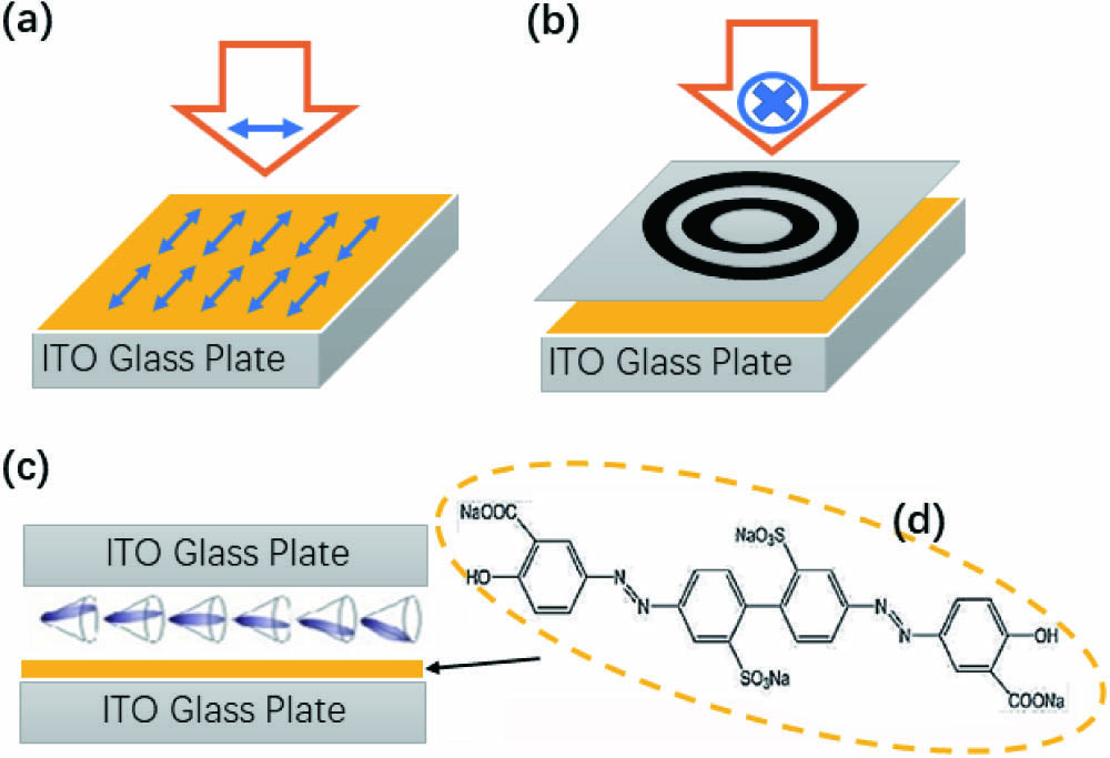
    Figure 1.Schematic representation of the two-step exposure technique for the patterned alignment layer of the FLC CDG. (a) The exposure of polarized UV on the SD1 substrate; (b) the exposure of the SD1 substrate with the mask; (c) the FLC CDG cell with a single-side alignment; (d) the chemical formula of the SD1.

    The SD1 aligning layer provides the orientation of the FLC helix perpendicular to the polarization of exposure, as shown in Fig. 1(a). Linearly polarized UV light with a uniform intensity (central wavelength is 365 nm and I=5.5mW/cm2) was applied to generate the first alignment direction [Fig. 1(a)]. Then, the alignment direction of the SD1 was re-aligned by the second exposure with the mask and polarization direction, which was rotated by 90° to create two perpendicularly aligned domains on the same substrate [see Fig. 1(b)]. The illuminated substrate was utilized to assemble a cell with an asymmetric configuration in which the surface aligning layer is only on one substrate, as shown in Fig. 1(c).

    Then the FLC material FD4004N (DIC, Japan) was filled into the prepared cell. The FLC material FD4004N has the following phase transition scheme: SmC*SmAN*Iso at the temperatures of 72°C, 85°C, and 105°C, respectively. The FLC helix pitch, the spontaneous polarization, and the tilt angle are equal to P0=350nm, PS61nC/cm2, and θ22.05°, respectively, at room temperature. The 9 μm spacers between the substrates were used to control the cell gap and maintain the optimized contrast between odd and even zones. Given the fact that the exposure dosage determines the photo-induced anchoring of the SD1 layer, the exposure time is optimized for alignment quality[23]. Considering the thickness and the elastic property of the FLC material, a UV dosage of 10J/cm2 was irradiated for creating the optimal aligning condition. In this case, a proper balance is achieved between the anchoring energy of the alignment layer and elastic energy of the helix in cells with a thickness much larger than the helical pitch.

    The fabricated device has perpendicular helix axes in the adjacent areas. The helical structure exists, maybe partially, without an external electric field. Figure 2(a) shows the textures of the FLC CDG with an aperture size of 4 mm under a polarizing optical microscope, and the top view of the helical orientations in odd and even zones. As is demonstrated in Fig. 2(b), the polarizer is placed parallel to the alignment direction of even zones, and the analyzer is arranged perpendicularly. When the applied voltage is above the helix unwinding field (typically ∼0.5 V/μm), the helical structure completely unwinds. Figures 2(c) and 2(e) represent the textures of the 9 μm thick cell with the applied voltage set at 15 V, and the helix is completely suppressed. In this case, a uniform orientation of the FLC molecules is realized. Only two directions of orientation are possible, which correspond to the polarities of the electric field. In the planar alignment of the configuration with the helical axis aligned parallel to the substrate surface, the uniform orientations of the FLC molecules are parallel to the substrate, but tilted by the cone angle θ. The molecular alignment in odd and even zones is always orthogonal to each other. Thus, the designed FLC CDG is polarization-independent[26]. The He–Ne laser with a beam expander and a diaphragm is employed in our experiment setup. With the half-wave condition satisfied, a π phase shift is achieved for the passing light between the odd and even domains. And then, the far-field diffraction patterns exhibit a uniform energy distribution, as shown in Fig. 3(a). The corresponding light intensity profile for the eight orders of diffractive patterns is shown in Fig. 3(b).

    (a) Microscopic photo of the FLC CDG under the crossed polarizer and analyzer. The horizontal yellow bar shows the scale ratio of 200 μm. Red arrows indicate the alignment directions. (b) Illustration of the molecule directions and the helical orientation with respect to the polarizer and analyzer in the odd and even zones. (c) and (e) are the textures of the FLC CDG under the electric field of two polarities; (d) and (f) represent the orientation of the FLC molecules for textures (c) and (e), respectively.

    Figure 2.(a) Microscopic photo of the FLC CDG under the crossed polarizer and analyzer. The horizontal yellow bar shows the scale ratio of 200 μm. Red arrows indicate the alignment directions. (b) Illustration of the molecule directions and the helical orientation with respect to the polarizer and analyzer in the odd and even zones. (c) and (e) are the textures of the FLC CDG under the electric field of two polarities; (d) and (f) represent the orientation of the FLC molecules for textures (c) and (e), respectively.

    For the eight-order FLC CDG, (a) the far-field diffraction patterns and (b) the corresponding light intensity profile.

    Figure 3.For the eight-order FLC CDG, (a) the far-field diffraction patterns and (b) the corresponding light intensity profile.

    Since the CDG is designed for a uniform energy distribution, further evaluations are provided using parameters including a diffraction efficiency (fraction of incident light diffracted out of the zero order) and uniformity. Given that the half-wave condition is satisfied, which is phase retardation different between odd and even zones matching 5λ/2, the efficiency and uniformity are expected to be high. The diffraction efficiency of the CDG, is defined as η=ΣIn/Iout, where ΣIn is the total intensity of all diffraction peaks and Iout is the output intensity. The measured magnitude of the efficiency is 84.5%, which is close to theoretical limits. The uniformity is defined as U=[max(In)min(In)]/[max(In)+min(In)], where max(In) and min(In) represent the maximum and minimum intensities of the diffraction peaks. The measured uniformity of the FLC CDG is 0.012.

    Fast response of the FLCs provides the device with fast switching. The assembled FLC CDG quickly switches between the diffractive and transmissive states in the configuration with the polarizer shift angle θ from alignment direction and no analyzer. In this configuration, with an electric field of one polarity, say positive field, even and odd zones correspond to no and ne, respectively, as shown in Fig. 2(d). Thus, the phase retardation difference is introduced between the even and odd zones. When the reverse electric field is applied to the CDG, the refractive indices of the even and odd zones are almost the same as shown in Fig. 2(f), and thus the phase and polarization of the odd and even zones are identical. In this case, it is the transmissive mode. It is also possible to obtain the switching between the diffractive and off states with the help of a crossed polarizer and analyzers[27].

    The response time is measured by detecting the intensity of the diffractive orders. The switching-on time is defined as the transmittance of diffractive orders rises from 10% to 90%, and the switching-off time corresponds to drop from 90% to 10%. The response versus voltage curve is shown in Fig. 4. When the applied electric field exceeds the critical value, the switching on and off times are nearly equal for the FLC. At an electric field of 4.3 V/μm, the response time for both τON and τOFF is around 64 μs. As shown in the insert of Fig. 4, the waveform of the electro-optical response measured at a driving frequency of 500 Hz exhibits good saturation. It is maintained with a driving frequency up to 3 kHz.

    Switching time of the FLC CDG versus applied electric field. The magnitude of the driving frequency is set at 500 Hz. The inset figure shows the electro-optical response of the diffraction pattern.

    Figure 4.Switching time of the FLC CDG versus applied electric field. The magnitude of the driving frequency is set at 500 Hz. The inset figure shows the electro-optical response of the diffraction pattern.

    In summary, we have shown a CDG diffraction from a switchable FLC cell by utilizing a two-step photoalignment technique. The proposed FLC CDG demonstrates a fast response time, a high diffraction efficiency, and uniformity. The achieved switching-on and -off time of 64 μs at the voltage of 4.3 V/μm shows the diffraction efficiency of 84.5%. The demonstrated properties of the CDG expand its enormous applications in photonics.

    References

    [1] D. Fattal, Z. Peng, T. Tran, S. Vo, M. Fiorentino, J. Brug, R. G. Beausoleil. Nature, 495, 348(2013).

    [2] H. Chen, Y. Weng, D. Xu, N. V. Tabiryan, S. T. Wu. Opt. Express, 24, 7287(2016).

    [3] M. Khorasaninejad, F. Capasso. Science, 358, eaam8100(2017).

    [4] S. V. Serak, D. E. Roberts, J.-Y. Hwang, S. R. Nersisyan, N. V. Tabiryan, T. J. Bunning, D. M. Steeves, B. R. Kimball. J. Opt. Soc. Am. B, 34, B56(2017).

    [5] P. Chen, L. L. Ma, W. Duan, J. Chen, S. J. Ge, Z. H. Zhu, M. J. Tang, R. Xu, W. Gao, T. Li, W. Hu, Y. Q. Lu. Adv. Mater., 30, 1705865(2018).

    [6] R. Xu, P. Chen, J. Tang, W. Duan, S.-J. Ge, L.-L. Ma, R.-X. Wu, W. Hu, Y.-Q. Lu. Phys. Rev. Appl., 10, 034061(2018).

    [7] P. Chen, S.-J. Ge, W. Duan, B.-Y. Wei, G.-X. Cui, W. Hu, Y.-Q. Lu. ACS Photon., 4, 1333(2017).

    [8] K. B. Doh, K. Dobson, T. C. Poon, P. S. Chung. Appl. Opt., 48, 134(2009).

    [9] Y. Shinoda, J. P. Liu, P. S. Chung, K. Dobson, X. Zhou, T. C. Poon. Appl. Opt., 50, B38(2011).

    [10] S. Zhao, P. S. Chung. Opt. Commun., 279, 1(2007).

    [11] Y. Zhang, N. Gao, C. Xie. Appl. Phys. Lett., 100, 041107(2012).

    [12] Y. Xu, X. Han, G. Li, J. Liu, K. Xia, J. Li. Opt. Eng., 55, 056101(2016).

    [13] F. J. Wen, Z. Chen, P. S. Chung. Appl. Opt., 49, 648(2010).

    [14] F. J. Wen, P. S. Chung. Appl. Opt., 47, 5197(2008).

    [15] C. Zhou, J. Jia, L. Liu. Opt. Lett., 28, 2174(2003).

    [16] S. Zhao, P. S. Chung. Opt. Lett., 31, 2387(2006).

    [17] U. Levy, B. Desiatov, I. Goykhman, T. Nachmias, A. Ohayon, S. E. Meltzer. Opt. Lett., 35, 880(2010).

    [18] I. Moreno, J. A. Davis, D. M. Cottrell, N. Zhang, X. C. Yuan. Opt. Lett., 35, 1536(2010).

    [19] D. Luo, X. W. Sun, H. T. Dai, H. V. Demir. Appl. Opt., 50, 2316(2011).

    [20] X. Wang, S. Wu, W. Yang, C. Yuan, X. Li, Z. Liu, M. Tseng, V. G. Chigrinov, H. Kwok, D. Shen, Z. Zheng. Polymers (Basel), 9, 380(2017).

    [21] Y. Liu, P. Chen, R. Yuan, C.-Q. Ma, Q. Guo, W. Duan, V. G. Chigrinov, W. Hu, Y.-Q. Lu. Opt. Express, 27, 36903(2019).

    [22] Q. Guo, X. Zhao, H. Zhao, V. G. Chigrinov. Opt. Lett., 40, 2413(2015).

    [23] Q. Guo, A. K. Srivastava, E. P. Pozhidaev, V. G. Chigrinov, H. S. Kwok. Appl. Phys. Express, 7, 021701(2014).

    [24] Q. Guo, K. X. Yan, V. Chigrinov, H. J. Zhao, M. Tribelsky. Crystals, 9, 470(2019).

    [25] E. A. Shteyner, A. K. Srivastava, V. G. Chigrinov, H.-S. Kwok, A. D. Afanasyev. Soft Matter, 9, 5160(2013).

    [26] W. Hu, A. Kumar Srivastava, X.-W. Lin, X. Liang, Z.-J. Wu, J.-T. Sun, G. Zhu, V. Chigrinov, Y.-Q. Lu. Appl. Phys. Lett., 100, 111116(2012).

    [27] F. Fan, L. Yao, X. Wang, L. Shi, A. Srivastava, V. Chigrinov, H.-S. Kwok, S. Wen. Crystals, 7, 79(2017).

    Qi Guo, Tian Liu, Xiaoqian Wang, Zhigang Zheng, Aleksey Kudreyko, Huijie Zhao, V. Chigrinov, Hoi-Sing Kwok. Ferroelectric liquid crystals for fast switchable circular Dammann grating [Invited][J]. Chinese Optics Letters, 2020, 18(8): 080002
    Download Citation