Quanan Chen, Chun Jiang, Kuankuan Wang, Miao Zhang, Xiang Ma, Ye Liu, Qiaoyin Lu, and Weihua Guo*
Abstract
A thermally tuned multi-channel interference widely tunable semiconductor laser is designed and demonstrated, for the first time to our knowledge, that realizes a tuning range of more than 45 nm, side-mode suppression ratios up to 56 dB, and Lorentzian linewidth below 160 kHz. AlGaInAs multiple quantum wells (MQWs) were used to reduce linewidth, which have a lower linewidth enhancement factor compared with InGaAsP MQWs. To decrease the power consumption of micro-heaters, air gaps were fabricated below the arm phase sections. For a 75 μm long suspended thermal tuning waveguide, about 6.3 mW micro-heater tuning power is needed for a round-trip phase change. Total micro-heater tuning power required is less than 50 mW across the whole tuning range, which is lower than that of the reported thermally tuned tunable semiconductor lasers.1. INTRODUCTION
Narrow-linewidth tunable lasers are indispensable key devices in long-haul high-speed coherent optical communication systems. For higher data rates, the requirement for narrow-linewidth tunable semiconductor lasers becomes more and more demanding [1]. Besides, to increase spectral efficiency further, higher-order modulation formats are used, which also strengthens the limitation of the laser linewidth [2]. External-cavity lasers make it easy to realize narrow linewidth due to their long cavities [3,4]. However, monolithic integrated tunable semiconductor lasers are more preferable for optical fiber communication systems, as they show advantages of low cost, small size, high reliability, and capability to integrate with other functional components. Normally, wavelength tuning of monolithic integrated tunable semiconductor lasers is achieved by carrier injection. Nevertheless, linewidth is significantly broadened by shot noise and losses arising from free carrier absorption, which is normally on the order of megahertz (MHz) [5–7]. In the past decade, great efforts have been made for monolithic integrated tunable semiconductor lasers to realize narrow linewidth.
For a distributed feedback (DFB) laser array, the most effective way to reduce linewidth is to increase the cavity length [8,9]. For distributed Bragg reflector (DBR)-type tunable semiconductor lasers, there are two ways to realize narrow linewidth in a wide wavelength tuning range. One common way is employing thermal tuning. Thermal tuning can eliminate the shot noise and the tuning-induced losses of current injection. Normally, a micro-heater is fabricated on top of the tuning waveguide to change the refractive index by temperature. In 1995, a super-structure grating DBR laser was reported to show linewidth lower than 400 kHz with thermal tuning [10]. However, the thermal tuning efficiency is extremely low because heat is largely dissipated through the InP substrate to the heat sink. To reduce the tuning powers with respect to power consumption, air gaps below the tuning waveguides are utilized to increase the thermal resistance. With the help of the air gaps, total thermal tuning power around 100 mW and narrow linewidth below 100 kHz were demonstrated for a sampled grating distributed Bragg reflector (SG-DBR) laser [11] and a modulated grating distributed Bragg reflector (MG-DBR) laser [12,13].
The Lorentzian linewidth of a single-mode laser can be expressed by the modified Schawlow–Townes formula [14]. The linewidth is enhanced by a factor of , where is the linewidth enhancement factor. Therefore, the other efficient way to reduce linewidth is using materials with lower linewidth enhancement factor. In comparison with InGaAsP multiple quantum wells (MQWs), AlGaInAs MQWs have a lower linewidth enhancement factor and show better high temperature performance, which make it easier to realize narrow linewidth [15]. A digital supermode distributed Bragg reflector (DS-DBR) laser was demonstrated to exhibit linewidth with AlGaInAs MQWs and a hybrid electrical and thermal tuning method [16].
Sign up for Photonics Research TOC. Get the latest issue of Photonics Research delivered right to you!Sign up now
In this paper, we demonstrate a narrow-linewidth thermally tuned multi-channel interference (MCI) widely tunable laser for the first time. To reduce the linewidth of the MCI laser, we use both AlGaInAs MQWs and thermal tuning. The laser realizes a tuning range of more than 45 nm, side-mode suppression ratios (SMSRs) up to 56 dB, and Lorentzian linewidth below 160 kHz. Due to the air gaps below the arm phase sections, total micro-heater tuning power under 50 mW is needed for wavelength tuning, which is lower than what has been reported in Refs. [11–13]. This paper is organized as follows: first, the laser design and fabrication are introduced; then, characterization results of the laser are shown and discussed; finally, a brief conclusion is given.
2. DEVICE DESIGN AND FABRICATION
A microscope image of the fabricated thermally tuned MCI laser is shown in Fig. 1. The laser is composed of a gain section and an MCI section. The gain section is 400 μm long. The MCI section is passive and includes a multi-mode interferometer (MMI) and eight arms with unequal length difference. To reflect the lights of the eight arms back into the gain section, a multi-mode interference reflector (MIR) is integrated at the rear of each arm. Eight arm phase sections are used to tune the phases of the eight arms independently. The gain section is surface ridge waveguide, and the passive sections are deep-ridge waveguides. To reduce the loss arising from mode mismatch between the surface and deep-ridge waveguides, a tapered shallow-deep transition structure was used to connect the shallow- and deep-ridge waveguides [17]. To select a designated longitudinal mode to lase, the eight arms have to be in phase at that mode, which can be realized by adjusting the phases of the eight arms. Only round-trip phase shift of each arm is enough for coarse tuning [18]. Fine-tuning of the longitudinal modes can be achieved by changing the working temperature of the chip.
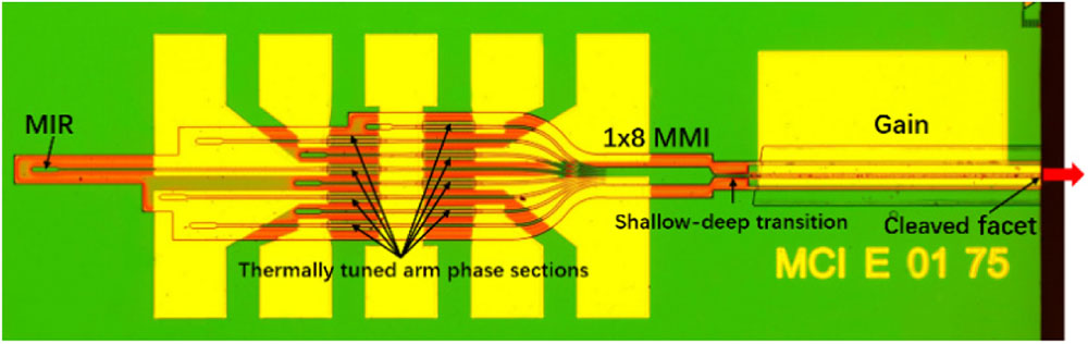
Figure 1.Microscope image of the fabricated thermally tuned MCI laser.
AlGaInAs MQWs are used to reduce linewidth and consist of five compressively strained wells providing optical emission near 1550 nm. A schematic drawing of the wafer structure is shown in Fig. 2. An offset quantum wells scheme was utilized to realize active-passive integration [19], which reduces the complexity and requirement of butt-joint epitaxial regrowth. AlGaInAs MQWs were deposited on a bulk 1.3Q InGaAsP waveguide layer. AlGaInAs MQWs in the passive sections were selectively removed by wet etching and then followed by a second epitaxial regrowth of the upper P-InP cladding layer and InGaAs contact layer.

Figure 2.Schematic drawing of the wafer structure.
Instead of current injection, thermal-optic effect is applied to change the refractive index of the arm phase sections. A metallic micro-heater is patterned on top of the deep-ridge waveguide. In order to increase the heating efficiency, an air gap is employed to separate the deep-ridge waveguide from the InP substrate, which was fabricated by etching an InGaAs sacrificial layer. The InGaAs sacrificial layer under the MQWs was grown in the first base epitaxial growth. The suspended thermal tuning waveguide cannot be too long because it may collapse during the fabrication. For the considerations of thermal tuning power and fabrication difficulty, we set the length of the suspended arm phase sections to be 75 μm after simulation and experiment. The fabrication processes of the suspended thermal tuning waveguide are shown in Fig. 3 and are described briefly as follows. First, a deep-ridge waveguide was defined by an i-line stepper and etched into the N-InP lower cladding layer [Figs. 3(a)–3(c)]; second, after removing the residual hard mask, a 600 nm thick hard-mask layer was deposited on the whole wafer [Fig. 3(d)]; then, two trenches were etched through the InGaAs sacrificial layer on both sides of the deep-ridge waveguide [Figs. 3(e) and 3(f)], and the lengths of the two trenches are the same as the micro-heater; finally, the InGaAs sacrificial layer was selectively removed by wet etching [Figs. 3(g) and 3(h)]. Deposition of a thick isolation layer was carried out to protect the suspended waveguide. Figure 4 shows scanning electron microscope (SEM) images of the top view, cross section, and side view of a suspended waveguide after wet etching of the InGaAs sacrificial layer. We can see that the thermal tuning waveguide was successfully separated from the substrate.
Figure 3.Fabrication processes of the suspended thermal tuning waveguide.
Figure 4.SEM images of the suspended thermal tuning waveguides after wet etching: (a) top view; (b) cross section; (c) side view.
We used heat transfer module in COMSOL Multiphysics to simulate temperature distribution in the thermal tuning waveguides with and without air gap when heating the micro-heater [20]. Because the micro-heaters are about 400 μm away from the gain section in our laser, heat crosstalk between the arm phase sections and the gain section is negligible compared with DBR-type tunable semiconductor lasers. Consequently, we only considered the heat transfer around the arm phase sections. In the simulation, the initial temperature value was set to be 20°C, and the temperature of the interface between the N-InP substrate and the carrier was fixed at 20°C. The two-dimensional static temperature distributions of the cross section at the middle of two 75 μm long thermal tuning waveguides with and without an air gap are shown in Fig. 5. As we can see, with the assistance of the air gap, heat mostly concentrates in the suspended waveguide area, while heat is dramatically conducted to the substrate for the thermal tuning waveguide without an air gap. Static temperature distribution along the center of the InGaAsP waveguide layer with different heating powers is extracted and shown in Fig. 6. For the suspended thermal tuning waveguide, the temperature along the waveguide is nonuniform and much higher, and it is the highest at the middle and decreases from the middle to both sides. For the thermal tuning waveguide without an air gap, the temperature along the waveguide is more uniform but much lower. It is estimated that thermal resistance of the suspended tuning waveguide is increased by a factor of 10 on average compared with the tuning waveguide without an air gap. Using the relationship between temperature and refractive index, we calculated the phase changes at different heating powers. The calculated results are shown in Fig. 7. About 6.1 mW heating power is needed for a round-trip phase change with an air gap. Because the maximal round-trip phase change needed for coarse tuning of each arm phase section is only , we can predict that the total thermal tuning powers of the MCI laser will not exceed 50 mW, which is pretty low with respect to power consumption.
Figure 5.Two-dimensional temperature distribution of the cross section at the middle of the thermal tuning waveguides: (a) with air gap; (b) without air gap.
Figure 6.Temperature distribution along the center of the InGaAsP waveguide layer with heating power increasing from 2 to 20 mW at a step of 2 mW: (a) with air gap; (b) without air gap.
Figure 7.Calculated phase changes of the thermal tuning waveguides with and without air gap at different heating powers.
3. DEVICE CHARACTERIZATION AND DISCUSSION
The laser chip was soldered onto an AlN carrier and then placed on a copper heat sink. Working temperature was controlled by a thermoelectric controller (TEC). As show in Fig. 8, output light was coupled into a single-mode fiber through two collimating lenses (L1 and L2). A 60 dB free-space isolator was used to prevent light from coupling back into the laser cavity. Threshold currents are typically between 15 and 20 mA. First, the phase tuning efficiency of the thermally tuned arm phase sections was measured. By heating one of the arm phase sections, we measured the output power and lasing wavelength above threshold current. As shown in Fig. 9, as the micro-heater power increases from 0 to 20 mW, the output power and lasing wavelength change periodically. One period corresponds to round-trip phase change. Therefore, it is estimated that about 6.3 mW tuning power is needed for a round-trip phase change. Besides, we can see that the lasing wavelength also increases slightly, which means that the temperature of the laser chip increases. This situation can be improved with better temperature control after packaging. Besides, we also measured amplified spontaneous emission (ASE) spectra below threshold current at different heating powers with only one arm phase section being heated up. Figure 10(a) shows a measured ASE spectrum below threshold current. The injection current of the gain section was 14 mA. By taking the Fourier transform of the measured ASE spectra, we can convert the space domain to the frequency domain as shown in Fig. 10(b). There are only six obvious peaks, and the second peak located at 1070 μm has the largest amplitude. The second peak is a combination of three cavities, because the length difference of the three cavities is so small that they overlap with each other in the frequency domain, which can be seen in Fig. 1. The lengths of the eight cavities converted from the Fourier transform of the measured ASE spectra agree well with the designed lengths. In addition, the round-trip phase changes of the eight arms can be extracted from the Fourier transform analysis, and the results are plotted in Fig. 10(c). The red line is the phase change of the heated arm, and the lines below blue dashed line are the phase changes of the other seven arms, which are not heated. We can see that phase of the heated arm increases when the micro-heater power increases from 0 to 20 mW. However, the phases of the other seven arms increase slowly, which mainly results from the increasing temperature of the laser chip. The micro-heater power needed for the round-trip phase is about 6.3 mW, which is equal to the power extracted from the output power and lasing wavelength changes measured above and close to the simulation result.
Figure 8.Experimental setups for characterization of the thermally tuned MCI laser, including wavelength characterization, spectral measurement, and linewidth measurement.
Figure 9.Output power and lasing wavelength versus micro-heater power of a heated arm phase section.
Figure 10.(a) Measured ASE spectrum below threshold current. Injection current of the gain section was 14 mA. (b) Fourier transform analysis of the ASE spectrum below threshold current. (c) Phase changes of the eight arms. The red line is the phase change of the heated arm, and the dashed line is .
We used an optimization-algorithm-based characterization scheme to make the MCI laser output any desired wavelength across the tuning range [21]. In the characterization processes, the heating powers of the eight micro-heaters were set between 0 and 8 mW so as to cover a round-trip phase change more than . The injection current of the gain section was kept constant at 90 mA, which was set to avoid heat saturation. With larger injection current, the output power will saturate, and the laser performance will deteriorate instead. With 90 mA injection current, the facet output power of the laser was estimated to be around 5 mW. Working temperature was set to be 20°C.
The fabricated MCI laser shows very good single-mode performance. A typical lasing spectrum of the thermally tuned MCI laser is shown in Fig. 11. The resolution of the optical spectrum analyzer was set to be 0.02 nm. The inset plot is measured from 1543 to 1547 nm. Mode spacing is about 0.28 nm. The SMSR is limited by the adjacent longitudinal mode and is about 55 dB. We characterized the laser at a 0.4 nm () wavelength spacing from 1535 to 1580.2 nm. Superimposed lasing spectra are shown in Fig. 12(a). The tuning range is more than 45 nm. The SMSRs and peak powers of the 114 wavelengths are shown in Fig. 12(b). The SMSRs are more than 52 dB across the tuning range and typically 56 dB around the gain peak. Power variation is within 1.5 dB. Although there is no common phase section, fine-tuning of the MCI laser can be achieved by changing the working temperature of the laser chip. We measured the relationship between lasing wavelength and chip temperature, which is shown is Fig. 13. The lasing wavelength is 1545 nm at 20°C. As the chip temperature increases, the lasing wavelength is red-shifted. The temperature coefficient is calculated to be about 0.11 nm/°C.
Figure 11.Typical lasing spectrum at wavelength 1545 nm. Resolution of the optical spectrum analyzer is 0.02 nm.
Figure 12.(a) Superimposed lasing spectra from 1535 to 1580.2 nm with a wavelength spacing of 0.4 nm; (b) corresponding SMSRs and peak powers.
Figure 13.Relationship between lasing wavelength and chip temperature.
The resistances of the 75 μm long micro-heaters are about 185 Ω. We calculated the total micro-heater tuning powers, which are shown in Fig. 14(a). The total micro-heater tuning powers are less than 50 mW for the 114 lasing wavelengths, which can meet the requirement of low power consumption of a small form-factor package. We measured the FM-noise spectrum with a self-homodyne optical receiver method [22]. The FM-noise spectrum of the MCI laser mainly contains three parts: the noise, white noise, and noises from the environment. The noises from the environment and the noise are generally below 100 MHz. The noises from the environment can be eliminated with effective electromagnetic shielding. A coherent communication system mainly concerns the white noise, which corresponds to the Lorentzian linewidth of the laser [23]. Therefore, the Lorentzian linewidth of the MCI laser is mainly measured. The Lorentzian linewidth was estimated from the frequency noises between 300 and 500 MHz. The results are given in Fig. 14(b). The linewidth is below 100 kHz at the short wavelength and increases at the long wavelength due to increased linewidth enhancement factor [24]. Maximum linewidth is below 160 kHz.
Figure 14.(a) Total micro-heater powers needed for the 114 wavelengths; (b) measured Lorentzian linewidth of the 114 wavelengths.
4. CONCLUSION
In conclusion, we have demonstrated a narrow-linewidth thermally tuned MCI widely tunable semiconductor laser. To reduce the laser linewidth, we used AlGaInAs MQWs and thermal tuning. Active-passive integration was realized by an offset quantum well scheme. The laser realizes stable single-mode lasing with a tuning range of more than 45 nm, SMSRs up to 56 dB, and Lorentzian linewidth below 160 kHz. Due to the air gaps below the arm phase sections, total micro-heater tuning power under 50 mW is needed for wavelength tuning, which is lower than the reported results of thermally tuned tunable semiconductor lasers. Only 6.3 mW is needed for a round-trip phase change, which is close to the simulation result. In our future work, we will further optimize the epitaxial structure and also reduce the loss of the MCI section. The quality factor of the laser cavity is expected to be improved so as to reduce the threshold current and reduce the linewidth as well. Also, packaging and reliability tests of the laser will be carried out in the near future. Compared with the DFB laser array and DBR-type tunable lasers, fabrication of the MCI laser is relatively simple because only conventional photolithography is needed. We believe that the MCI laser will have potential applications in optical fiber communication systems and photonic integrated circuits.
Acknowledgment
Acknowledgment. We thank Yan Zhu in the Micro and Nano Fabrication and Measurement Laboratory for the support in the use of scanning electron microscope.
References
[1] M. C. Larson. Widely tunable semiconductor lasers. Optical Fiber Communication Conference, Tu2H.1(2014).
[2] M. Seimetz. Laser linewidth limitations for optical systems with high-order modulation employing feed forward digital carrier phase estimation. Optical Fiber Communication/National Fiber Optic Engineers Conference, OTuM2(2008).
[3] C. Y. Ye. Tunable External Cavity Diode Lasers(2004).
[4] A. Daiber. Narrow-linewidth tunable external cavity laser for coherent communication. Photonics Conference, 447-448(2014).
[5] M. C. Amann, R. Schimpe. Excess linewidth broadening in wavelength-tunable laser diodes. IEEE Electron. Lett., 26, 279-280(1990).
[6] S. Nakagawa, G. Fish, A. Dahl, P. Koh, C. Schow, M. Mach, L. Wang, R. Yu. Phase noise of widely-tunable SG-DBR laser. Optical Fiber Communications Conference, ThF2(2003).
[7] R. T. Watts, K. Shi, Y. L. Yu, L. P. Barry. Detailed experimental phase noise characterization of Y-branch lasers for use in coherent communication systems. Optical Fiber Communication Conference & Exposition / National Fiber Optic Engineers Conference, JW2A.32(2013).
[8] H. Ishii, K. Kasaya, H. Oohashi. Narrow spectral linewidth operation (<160 kHz) in widely tunable distributed feedback laser array. IEEE Electron. Lett., 46, 714-715(2010).
[9] A. Kasukawa, T. Mukaihara. High power, narrow linewidth tunable lasers. OptoElectronics and Communication Conference and Australian Conference on Optical Fibre Technology, 965-966(2014).
[10] H. Ishii, F. Kano, Y. Tohmori, Y. Kondo, T. Tamamura, Y. Yoshikuni. Narrow spectral linewidth under wavelength tuning in thermally tunable super-structure-grating (SSG) DBR lasers. IEEE J. Sel. Top. Quantum Electron., 1, 401-407(1995).
[11] M. C. Larson. Narrow linewidth tunable DBR lasers. International Semiconductor Laser Conference, TuC2(2016).
[12] U. Eriksson, J. Wesström, Y. T. Liu, S. Hammerfeldt, M. Hassler, B. Stoltz, N. Carlsson, S. Siraj, E. Goobar, Y. Matsui. High performance narrow linewidth thermally tuned semiconductor laser. European Conference on Optical Communication, 1-3(2015).
[13] Y. Matsui, U. Eriksson, J. Wesstrom, Y. T. Liu, S. Hammerfeldt, M. Hassler, B. Stoltz, N. Carlsson, S. Siraj, E. Goobar. Narrow linewidth tunable semiconductor laser. Compound Semiconductor Week, 1-2(2016).
[14] C. Henry. Theory of the linewidth of semiconductor lasers. IEEE J. Quantum Electron., 18, 259-264(1982).
[15] S. C. Davies, N. D. Whitbread, A. J. Ward, M. Arnold, R. A. Griffin, M. J. Wale. Reduce Lorentzian linewidth for monolithic widely tunable C-band lasers utilizing InGaAlAs/InP active region. Lasers & Electro-optics Europe and 12th European Quantum Electronics Conference, CI3_3(2011).
[16] S. C. Davies, R. A. Griffin, A. J. Ward, N. D. Whitbread, I. Davies, L. Langley, S. Fourte, J. Mo, Y. Xu, A. Carter. Narrow linewidth, high power, high operating temperature digital supermode distributed Bragg reflector laser. 39th European Conference & Exhibition on Optical Communication, 1-3(2013).
[17] Q. A. Chen, C. Jiang, X. Ma, Y. Liu, D. T. Yang, Q. Y. Lu, W. H. Guo. 1 × 8 MMI based multi-channel interference laser integrated with SOA through a 2-port multimode interference reflector. Opt. Express, 26, 19940-19949(2018).
[18] Q. A. Chen, Q. Y. Lu, W. H. Guo. Theory and simulation of multi-channel interference (MCI) widely tunable lasers. Opt. Express, 23, 18040-18051(2015).
[19] Q. A. Chen, X. Ma, W. Sun, Y. Liu, G. H. Liu, G. Y. Zhao, Q. Y. Lu, W. H. Guo. Demonstration of multi-channel interference widely tunable semiconductor laser. IEEE Photon. Technol. Lett., 28, 2862-2865(2016).
[20] X. M. Han, Q. Cheng, F. Liu, Y. L. Yu. Numerical analysis on thermal tuning efficiency and thermal stress of a thermally tunable SG-DBR laser. IEEE Photon. J., 8, 1501512(2016).
[21] Q. A. Chen, G. H. Liu, Q. Y. Lu, W. H. Guo. Optimization algorithm based characterization scheme for tunable semiconductor lasers. Opt. Express, 24, 20982-20992(2016).
[22] T. N. Huynh, L. Nguyen, L. P. Barry. Phase noise characterization of SGDBR lasers using phase modulation detection method with delayed self-heterodyne measurements. IEEE J. Lightwave Technol., 31, 1300-1308(2013).
[23] L. B. Mercer. 1/f frequency noise effects on self-heterodyne linewidth measurements. IEEE J. Lightwave Technol., 9, 485-493(1991).
[24] W. H. Guo, D. C. Byrne, Q. Y. Lu, B. Corbett, J. F. Donegan. Fabry–Pérot laser characterization based on the amplified spontaneous emission spectrum and the fourier series expansion method. IEEE J. Sel. Top. Quantum Electron., 17, 1356-1363(2011).

