• Laser & Optoelectronics Progress
  • Vol. 58, Issue 9, 0923002 (2021)
Xianxiu Zhang1, Cunyi Wang2, Pei Yuan1、*, Dongliang Zhang1, and Yongqian Wang1
Author Affiliations
  • 1Key Laboratory of the Ministry of Education for Optoelectronic Measurement Technology and Instrument, Beijing Information Science & Technology University, Beijing 100192, China
  • 2Mechanical Products Division, Beijing Satellite Manufacturing Co. LTD, Beijing 100190, China
  • show less
    DOI: 10.3788/LOP202158.0923002 Cite this Article Set citation alerts
    Xianxiu Zhang, Cunyi Wang, Pei Yuan, Dongliang Zhang, Yongqian Wang. Array Waveguide Gratings for FBG Demodulation Design and Performance Analysis[J]. Laser & Optoelectronics Progress, 2021, 58(9): 0923002 Copy Citation Text show less
    AWG wavelength demodulation system. (a) Basic component; (b) schematic of principle
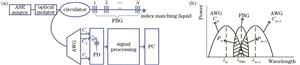
    Fig. 1. AWG wavelength demodulation system. (a) Basic component; (b) schematic of principle
    Relationship between AWG demodulation function and FBG central wavelength at different crosstalk
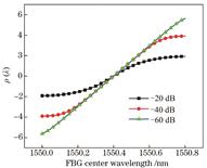
    Fig. 2. Relationship between AWG demodulation function and FBG central wavelength at different crosstalk
    Relationship between AWG demodulation function and FBG central wavelength at different insertion loss
    Fig. 3. Relationship between AWG demodulation function and FBG central wavelength at different insertion loss
    Relationship between AWG demodulation function and FBG central wavelength at different half-peak full widths
    Fig. 4. Relationship between AWG demodulation function and FBG central wavelength at different half-peak full widths
    Relationship between normalized power of waveguide output and bending radius
    Fig. 5. Relationship between normalized power of waveguide output and bending radius
    Relationship between normalized output power of waveguide and length of tapered waveguide
    Fig. 6. Relationship between normalized output power of waveguide and length of tapered waveguide
    Simulation results of light field coupling of adjacent waveguides. (a) Waveguide spacing is 5 μm; (b) waveguide spacing is 10 μm; (c) relationship between waveguide spacing and normalized power
    Fig. 7. Simulation results of light field coupling of adjacent waveguides. (a) Waveguide spacing is 5 μm; (b) waveguide spacing is 10 μm; (c) relationship between waveguide spacing and normalized power
    Variation of output waveforms with different array waveguide numbers
    Fig. 8. Variation of output waveforms with different array waveguide numbers
    Variation of output waveform of different diffraction orders
    Fig. 9. Variation of output waveform of different diffraction orders
    Variation of output waveform with different opening widths
    Fig. 10. Variation of output waveform with different opening widths
    AWG map and spectrum. (a) AWG design layout; (b) AWG spectrogram
    Fig. 11. AWG map and spectrum. (a) AWG design layout; (b) AWG spectrogram
    ParamenterValue
    Number of channels16
    Central wavelength /nm1550
    Channel spacing /nm0.8
    Free spectral range /nm16.1387
    Diffraction order95
    Length increment /nm100.6005255
    Pitch of adjacent arrayed waveguides /nm9
    Pitch of adjacent input (output) waveguides /nm7
    Length of FPR /nm1205.155
    Number of arrayed waveguides49
    Table 1. Main parameters of AWG
    Xianxiu Zhang, Cunyi Wang, Pei Yuan, Dongliang Zhang, Yongqian Wang. Array Waveguide Gratings for FBG Demodulation Design and Performance Analysis[J]. Laser & Optoelectronics Progress, 2021, 58(9): 0923002
    Download Citation