
Han Wu, Weizhe Wang, Bo Hu, Yang Li, Kan Tian, Rui Ma, Chunxiao Li, Jun Liu, Jiyong Yao, Houkun Liang. Widely tunable continuous-wave visible and mid-infrared light generation based on a dual-wavelength switchable and tunable random Raman fiber laser[J]. Photonics Research, 2023, 11(5): 808
- Photonics Research
- Vol. 11, Issue 5, 808 (2023)
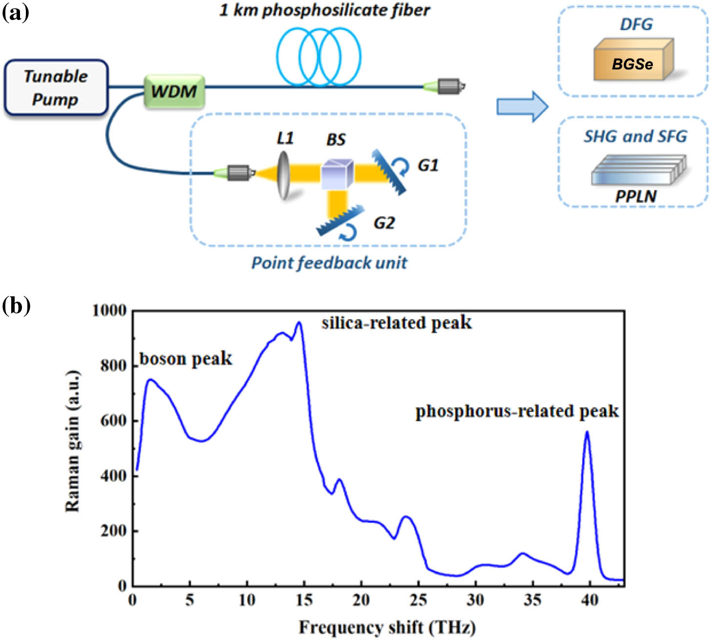
Fig. 1. (a) Experimental setup for the dual-wavelength switchable and tunable RRFL. G, grating; WDM, wavelength-division multiplexer; BS, 1:1 beam splitter; L, lens. (b) Raman gain spectrum of the used phosphosilicate fiber.
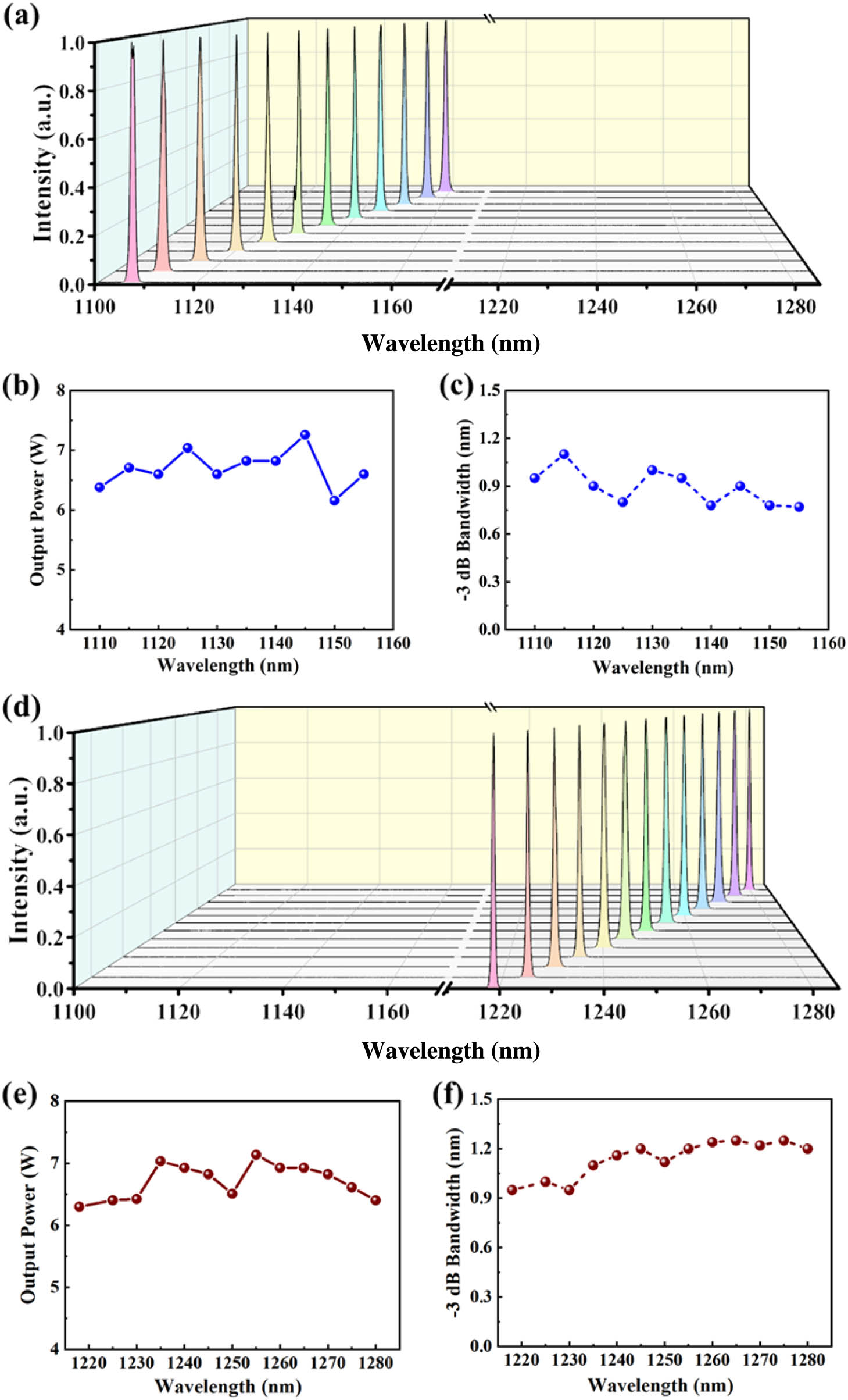
Fig. 2. (a) Spectra of the wavelength tunable RRFL based on the silica-related Raman peak with a wavelength tuning range from 1105 to 1160 nm. (b) Output powers of the wavelength tunable RRFL based on the silica-related Raman peak as a function of center wavelengths. (c) − 3 dB − 3 dB
Fig. 3. (a) Spectra of the dual-wavelength switchable and tunable RRFL with phosphosilicate fiber under dual-wavelength operation. (b) Output powers of the dual-wavelength laser with different wavelength pairs. (c) − 3 dB
Fig. 4. (a) Spectra of the dual-wavelength separation tunable RRFL with phosphosilicate fiber. (b) Output powers of the dual-wavelength separation tunable RRFL with different wavelength separations.
Fig. 5. (a) Experiment setup of the wavelength tunable CW visible light generation. (b) The experimentally measured spectra of the tunable CW visible light from 560 to 630 nm. (c) The output power of the tunable CW visible light as a function of the center wavelength. The green and red shades represent the visible components generated by the SHG of the single-wavelength tunable RRFL based on the silica-related Raman peak or phosphorus-related Raman peak, respectively, while the yellow shadow represents the visible components generated by the SFG of the dual-wavelength tunable RRFL. (d) Photograph of the wavelength tunable CW visible light with different center wavelengths.
Fig. 6. (a) Experimental setup of the wavelength tunable CW MIR light generation. Inset: transmission spectrum of coated BGSe crystal. (b) The experimentally measured spectra of the CW MIR light from 10.7 to 12.3 μm. (c) The calculated (red) and measured (blue) Type I (e-e-o) phase-matching curves of BGSe with a fixed signal wavelength of 1238 nm. Ge, germanium filter; C, chopper; MCT, HgCdTe detector; PA, preamplifier.
Fig. 7. Schematic diagram of dual-wavelength switchable and tunable RRFL with all-fiber structure. WDM, wavelength-division multiplexer; VOA, variable optical attenuator.
|
Table 1. Phase-Matching Conditions in PPLN Crystal Array

Set citation alerts for the article
Please enter your email address
© Copyright 2018-2021 | Chinese Laser Press. All Rights Reserved 沪ICP备15018463号-20