
Yiwei Zhang, Bangyi Tao, Zhihua Mao, Haiqing Huang, Qiankun Zhu, Fang Gong. Polarization Characteristics of Ultraviolet Bands Observed by Ocean Color Satellites[J]. Acta Optica Sinica, 2020, 40(6): 0601001
- Acta Optica Sinica
- Vol. 40, Issue 6, 0601001 (2020)
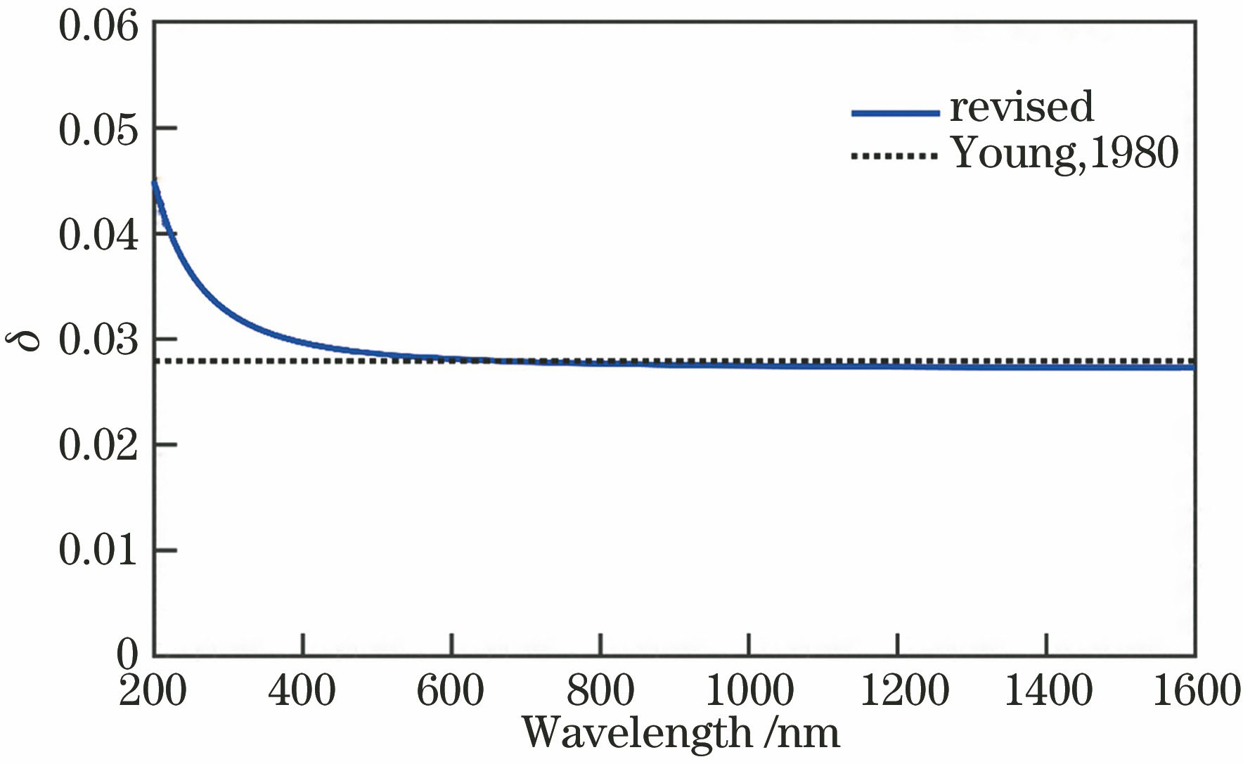
Fig. 1. Depolarization factor before and after modification
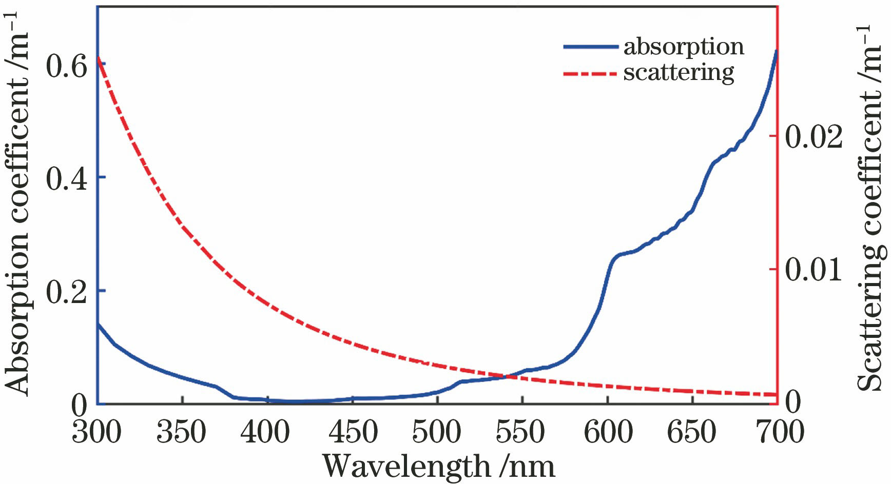
Fig. 2. Absorption and scattering coefficients of pure water
Fig. 3. Relative errors of Rayleigh scattering calculations for VIIRS 410 nm band with different solar zenith angles. (a) 0°; (b) 30°; (c) 60°
Fig. 4. Comparisons of LQ component of Stokes vector between the Rayleigh look-up-table for VIIRS 410 nm band with OSOAA calculations with different solar zenith angles. (a) 0°; (b) 30°; (c) 60°
Fig. 5. Comparisons of LU component of Stokes vector between the Rayleigh look-up-table for VIIRS 410 nm band with OSOAA calculations with different solar zenith angles. (a) 0°; (b) 30°; (c) 60°
Fig. 6. Geometry dependent distribution of satellite sensed DOP of atmospheric molecular scattering radiation. (a)(c)(e) Simulated light wavelength is 355 nm; (b)(d)(f) simulated light wavelength is 385 nm* denotes the sun, polar radius denotes viewing zenith angle θ, and polar angle denotes relative angle Δφ
Fig. 7. Wavelength dependent of satellite sensed atmospheric molecular scattering radiation. (a) Total reflectance and DOP; (b) total radiance and LPR (the solar zenith angle θ0=30°, viewing zenith angle θ=30°, relative azimuth angle Δφ=135°)
Fig. 8. Wavelength dependent of satellite sensed scattering radiation varied by aerosol relative humidity. (a) Total reflectance; (b) DOP (M30, M70 and M95 respectively denote the maritime aerosol with a relative humidity of 30%, 70% and 95%,the aerosol optical depth τ550=0.2 and the geometry conditions are the same as in Fig. 7 )
Fig. 9. Wavelength dependent of satellite sensed scattering radiation varied by aerosol optical depth. (a) Total reflectance; (b) DOP (the aerosol relative humidity is 70%, and the geometry conditions are the same as in Fig. 7 )
Fig. 10. Influence of air-sea interface on the satellite sensed scattering radiation at different wavelengths. (a) Total reflectance; (b) DOP (the geometry conditions are the same as in Fig. 7 )
Fig. 11. Influence of classical water on the satellite sensed scattering radiation at different wavelengths. (a) Total reflectance; (b) DOP(the geometry conditions are the same as in Fig. 5 )
Fig. 12. Influence of polarization feature on the model simulation. (a) Covered area of selected VIIRS and OMPS image; (b) selected S region located in the VIIRS image; (c) comparison of simulated total reflectance of S region at different wavelengths

Set citation alerts for the article
Please enter your email address
© Copyright 2018-2021 | Chinese Laser Press. All Rights Reserved 沪ICP备15018463号-20