Author Affiliations
1Institute of Advanced Photonics, School of Physics, Harbin Institute of Technology, Harbin 150001, China2School of Optoelectronic Engineering and Instrumentation Science, Dalian University of Technology, Dalian 116024, China3Collaborative Innovation Center of Extreme Optics, Shanxi University, Taiyuan 030006, Chinashow less
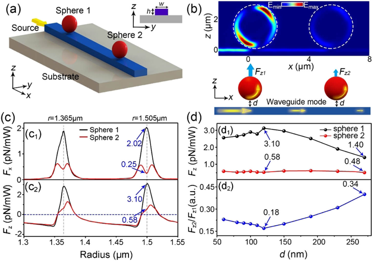
Fig. 1. Schematic and performances of resonant optical manipulation using the traditional optical waveguide. (a) Schematic of optical manipulation based on a strip waveguide (GaAs). The parameters are w=1 μm, h=0.2 μm, and light source frequency of f=315 THz. The two red spheres are to be manipulated in water. (b) The resonance of sphere 1 with the incident light generates a large repulsive force Fz1. The repulsive force Fz2 on sphere 2, however, is 1 order smaller than Fz1, because the guiding mode is greatly scattered by sphere 1. (c) Optical forces of Fx (upper part) and Fz (lower part) as a function of particle radius r. (d) Resonance force Fz on the two particles (upper part) and the ratio Fz2/Fz1 (lower part) as a function of the distance d between the waveguide and the particle.
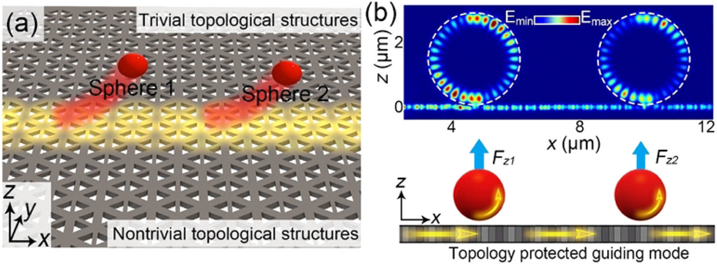
Fig. 2. Schematic of resonant optical manipulation using a topology-protected guiding channel. (a) The proposed new system is based on a topological photonic structure (the gray substrate), which supports a topology-protected guiding mode. Both sphere 1 and sphere 2 (the red spheres) are resonantely repelled from the substrate. (b) When particle 1 resonantly interacts with the incident light, a large repulsive force Fz1 is obtained. At the same time, the optical force Fz2 on particle 2 is also large enough, because the topologically protected mode almost keeps its original form after the resonant interaction with sphere 1. This merit makes multiple and parallel resonant optical manipulation possible.
Fig. 3. Structure, parameter, and performance of the topologically protected guiding channel. (a) Schematic of the topological photonic structure composed of two different honeycomb lattices. a0 is the lattice constant. S is the side lengths of the triangular holes (equilateral triangle). h is the thickness of the structure. a1 is the relative position of the triangular hole to the center of the unit cell. When a1:a0>1∶3, we say that the structure is expanded. On the contrary, it is a shrunken one. The parameters used are a0=445 nm, h=0.2 μm, S=140 nm. (b) Corresponding band structure of the TE modes along the x direction (see the inset). Crossing of the two edge states in the band gap is the character of topologically protected edge states. The frequency of the crossing point is at about 315 THz. (c) Electric field distribution of the light propagation in the topological photonic structure at the frequency of 315 THz. Owing to the topology-protected feature, the propagation of the light field is immune to the local defects (red-dotted box) and sharp turns and can be perfectly transmitted without obvious loss or backscattering.
Fig. 4. Optical forces on two spheres using the topological structure designed in Fig. 2(a). (a) Optical forces Fx and Fz as functions of particle radius r at the source frequency of 315 THz. Comparing the forces on particle 1, the forces on particle 2 are decreased moderately only due to the topologically protected feature of the guiding channel. Note that the optical force repeats periodically with the radius, showing one period only here. The two particles are to be manipulated in water. (b) Cross section of the electric field distribution on the x−z plane when the two particles are trapped on the topological PC structure. The radii of the spheres in (b1) and (b2) correspond to the points A and B marked in (a). (c) Resonant optical force Fz on the two particles (upper part) and the ratio of Fz2/Fz1 (lower part) at various distances d. (d) The ratios of optical forces on the nth particle to the first particle when ten particles are simultaneously manipulated on the topological (red curve) and ordinary (blue curve) waveguides. The curve decay rate represents the perturbation degree of the particles to the transmitted light.
Fig. 5. Dynamics of the resonant multiparticle sorting using the topological photonic slab. (a) Schematic of multiparticle optical sorting scheme using the topological structure, where a mixture of the three types of particles A, B, C marked in Fig. 4(a2) is randomly placed on the surface of the substrate. (b) Trajectories of mass center of the four type A particles (A1, A2, A3, and A4) as a function of time. (c) Temporal evolution of total force on the type-A particles. The forces on all particles on the slab are calculated simultaneously. (d) Temporal evolution of the total force on the type B particle of PB. It is noted that Ftotal,x and Ftotal,y are almost totally overlaped and both are nearly zero.