• Laser & Optoelectronics Progress
  • Vol. 55, Issue 4, 041401 (2018)
Liangliang Yang1, Luo Zhang1, Haihong Zhu1、*, Jie Yin1, Linda Ke1, and Xiaoyan Zeng1
Author Affiliations
  • 1 Shanghai Spaceflight Precision Machinery Institute, Shanghai 201600, China
  • 1 Wuhan National Laboratory for Optoelectronics, Huazhong University of Science and Technology, Wuhan, Hubei 430074, China
  • show less
    DOI: 10.3788/LOP55.041401 Cite this Article Set citation alerts
    Liangliang Yang, Luo Zhang, Haihong Zhu, Jie Yin, Linda Ke, Xiaoyan Zeng. Influences of Lens Distance and Tilt Angle Between Beam Expanders on Laser Focusing Characteristics[J]. Laser & Optoelectronics Progress, 2018, 55(4): 041401 Copy Citation Text show less
    Optical system diagram for laser processing
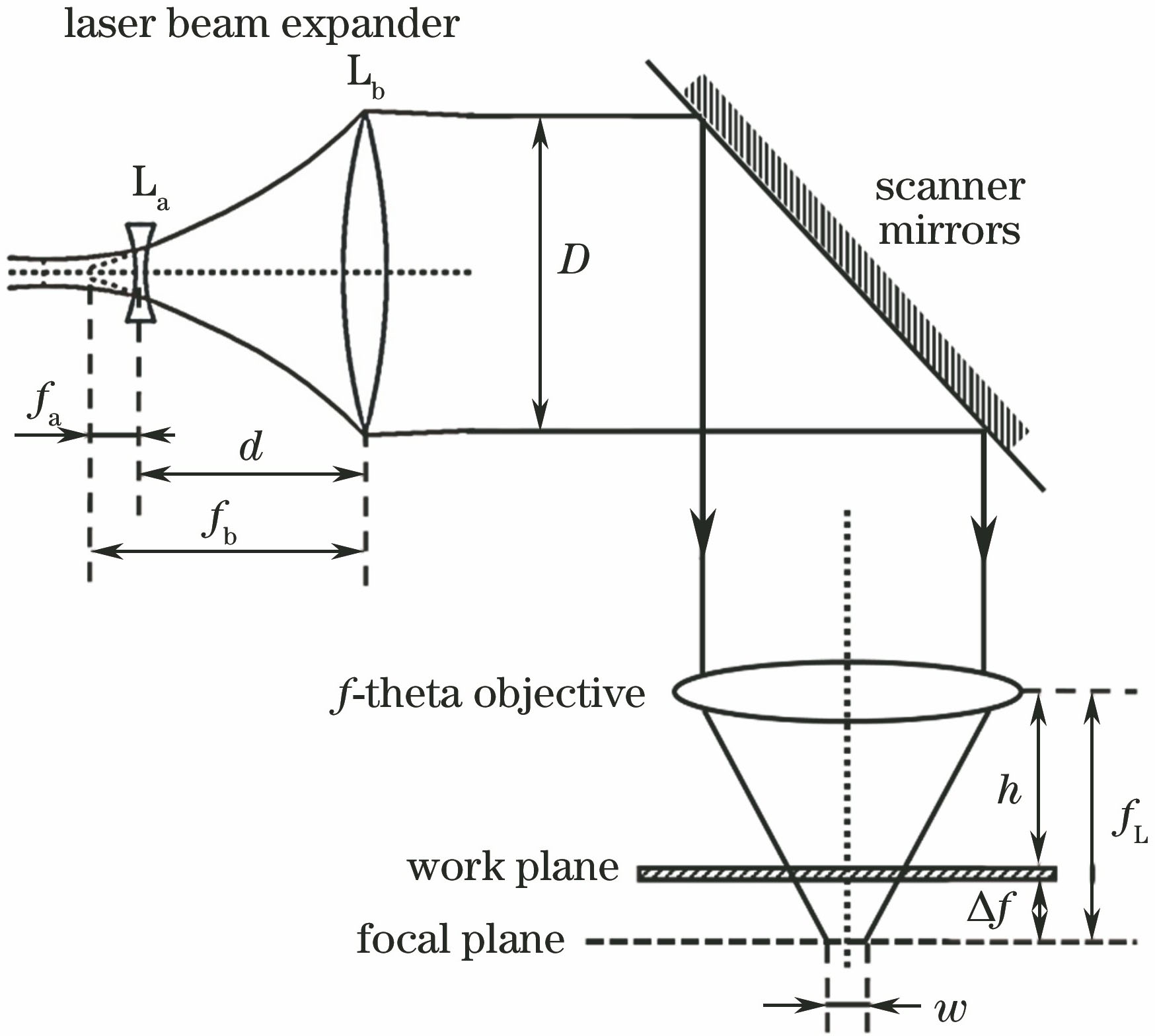
    Fig. 1. Optical system diagram for laser processing
    Beam expanders commonly used in laser processing. (a) Kepler system; (b) Galileo system
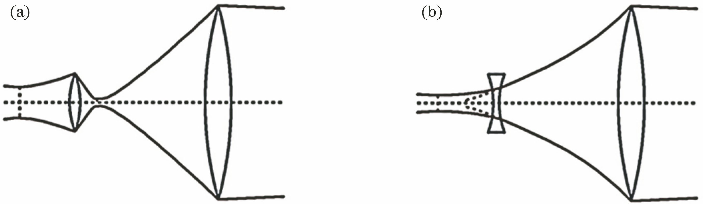
    Fig. 2. Beam expanders commonly used in laser processing. (a) Kepler system; (b) Galileo system
    Schematic of optical system with sequence mode
    Fig. 3. Schematic of optical system with sequence mode
    Diagram of optical system with non-sequence mode
    Fig. 4. Diagram of optical system with non-sequence mode
    Relationship between defocusing amount and distance between beam expanders
    Fig. 5. Relationship between defocusing amount and distance between beam expanders
    Schematic of tilt angle of beam expander
    Fig. 6. Schematic of tilt angle of beam expander
    Relationship among focal length, defocusing amount and tilt angle of beam expander
    Fig. 7. Relationship among focal length, defocusing amount and tilt angle of beam expander
    Relationship among peak power, spot diameter and distance between beam expanders
    Fig. 8. Relationship among peak power, spot diameter and distance between beam expanders
    Relationship among peak power, spot diameter and tilt angle of beam expander
    Fig. 9. Relationship among peak power, spot diameter and tilt angle of beam expander
    (a) Distribution of spot energy at different lens distances; (b) distribution of spot energy at different tilt angles; (c) relationship between spot center position and tilt angle of beam expander
    Fig. 10. (a) Distribution of spot energy at different lens distances; (b) distribution of spot energy at different tilt angles; (c) relationship between spot center position and tilt angle of beam expander
    (a) Schematic of experimental setup for measuring focus position; (b) schematic of measuring method; (c) relationship between defocusing amount and lens distance measured in experiment
    Fig. 11. (a) Schematic of experimental setup for measuring focus position; (b) schematic of measuring method; (c) relationship between defocusing amount and lens distance measured in experiment
    Schematic of experimental setup for measuring spot energy distribution
    Fig. 12. Schematic of experimental setup for measuring spot energy distribution
    Distributions of spot energy under different lens distances. (a) Δd=1.0 mm; (b) Δd=0.2 mm; (c) Δd=-0.2 mm; (d) Δd=-1.0 mm
    Fig. 13. Distributions of spot energy under different lens distances. (a) Δd=1.0 mm; (b) Δd=0.2 mm; (c) Δd=-0.2 mm; (d) Δd=-1.0 mm
    SurfaceRadius /mmThickness /mmGlassSemi-diameter /mm
    OBJInfinityInfinity-0.000
    STOInfinity5.000-2.500
    2-3.8005.200N-BK73.500
    3-10.45026.100-5.000
    450.6005.100N-BK712.500
    5-50.60050.000-12.500
    6Infinity50.000-10.868
    761.0267.500BK715.000
    8-44.8422.500SF515.000
    9-131.72695.726-15.000
    ImageInfinity--9.826
    Table 1. Parameters of optical system with sequence mode
    ItemObject typeReference objectzpositionMaterial
    1Source Gaussian00-
    2Detector rect05.000-
    3Standard lens210.000N-BK7
    4Standard lens331.300N-BK7
    5Detector rect455.100-
    6Standard lens550.000BK7
    7Standard lens67.500SF5
    8Detector rect798.226-
    Table 2. Parameters of optical system with non-sequential mode
    ItemObject typeReference objectzpositionTilt angle /(°)
    1Source Gaussian000
    2Detector rect05.0000
    3Standard lens015.0005
    4Standard lens046.3000
    5Detector rect0101.4000
    6Standard lens0151.4000
    7Standard lens0158.9000
    8Detector rect0257.1260
    Table 3. Parameters of optical system with non-sequential mode when lens tilt angle is changed
    DetectorSpot distribution on xy planeSpot distribution onx-axis (or y-axis)Stereogram of distributionof spot irradiance
    2(10 mm×10 mm)
    5(30 mm×30 mm)
    8(4 mm×4 mm)
    Table 4. Spot energy distributions in initial position (after filtering)
    Liangliang Yang, Luo Zhang, Haihong Zhu, Jie Yin, Linda Ke, Xiaoyan Zeng. Influences of Lens Distance and Tilt Angle Between Beam Expanders on Laser Focusing Characteristics[J]. Laser & Optoelectronics Progress, 2018, 55(4): 041401
    Download Citation