• High Power Laser Science and Engineering
  • Vol. 7, Issue 3, 03000e38 (2019)
I. V. Aleksandrova and E. R. Koresheva
Author Affiliations
  • Lebedev Physical Institute, Russian Academy of Sciences, Moscow 119991, Russia
  • show less
    DOI: 10.1017/hpl.2019.23 Cite this Article Set citation alerts
    I. V. Aleksandrova, E. R. Koresheva. Advanced fuel layering in line-moving, high-gain direct-drive cryogenic targets[J]. High Power Laser Science and Engineering, 2019, 7(3): 03000e38 Copy Citation Text show less
    A high-gain direct-drive target design proposed for a 1.3 MJ KrF laser[7].
    Fig. 1. A high-gain direct-drive target design proposed for a 1.3 MJ KrF laser[7].
    The phase state of $\text{D}_{2}$ fuel in the BODNER-Target upon cooling down. (a) PVT-diagram ($T_{\text{S}}$ is the temperature of fuel separation into the liquid and vapor phases). (b) Fuel state in the shell just before the FST layering versus the initial target temperature $T_{\text{in}}$: (1) gaseous fuel ($T_{\text{in}}>T_{\text{CP}}=38.34$ K), (2) compressed liquid ($36.5~\text{K}\sim T_{\text{S}}, $12.5~\text{atm}), (3) liquid $+$ vapor ($18.73~\text{K}=T_{\text{TP}}, $P atm).
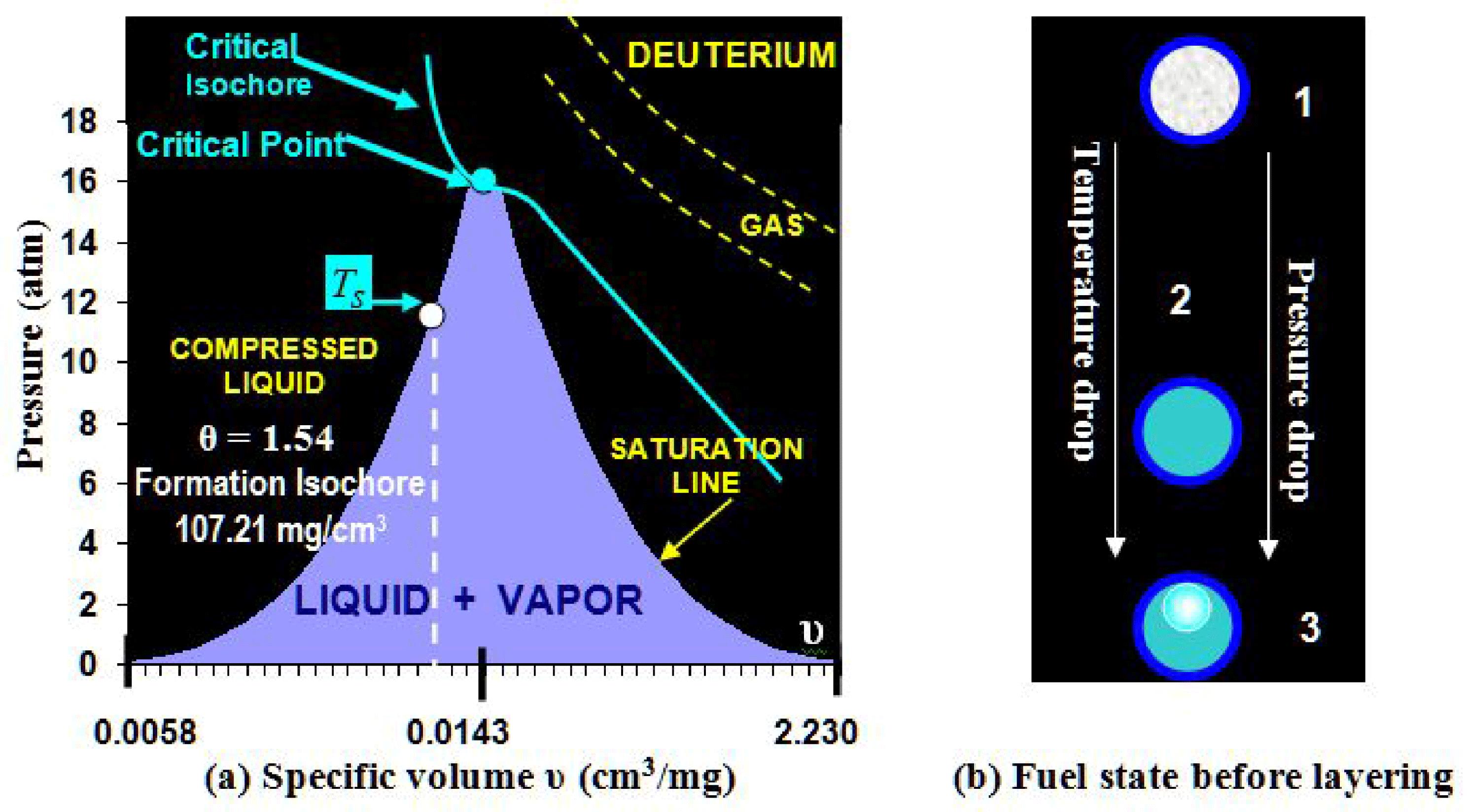
    Fig. 2. The phase state of $\text{D}_{2}$ fuel in the BODNER-Target upon cooling down. (a) PVT-diagram ($T_{\text{S}}$ is the temperature of fuel separation into the liquid and vapor phases). (b) Fuel state in the shell just before the FST layering versus the initial target temperature $T_{\text{in}}$: (1) gaseous fuel ($T_{\text{in}}>T_{\text{CP}}=38.34$  K), (2) compressed liquid ($36.5~\text{K}\sim T_{\text{S}}, $12.5~\text{atm}), (3) liquid $+$ vapor ($18.73~\text{K}=T_{\text{TP}}, $P<12.5$  atm).
    The FST layering method provides rapid symmetrization and freezing of solid ultrafine fuel layers. (a) Schematic of the FST layering module. (b) Target before layering (‘liquid $+$ vapor’ fuel state). (c) Target after FST layering (uniform solid layer). (d) Single-spiral LC (1) in the working assembly. (e) Single-spiral LC (1) shown with magnification. (f) Double-spiral LC.
    Fig. 3. The FST layering method provides rapid symmetrization and freezing of solid ultrafine fuel layers. (a) Schematic of the FST layering module. (b) Target before layering (‘liquid $+$ vapor’ fuel state). (c) Target after FST layering (uniform solid layer). (d) Single-spiral LC (1) in the working assembly. (e) Single-spiral LC (1) shown with magnification. (f) Double-spiral LC.
    The gas pressure in the shell versus the fuel density near the critical point for (a) $\text{D}_{2}$ and (b) D–T.
    Fig. 4. The gas pressure in the shell versus the fuel density near the critical point for (a) $\text{D}_{2}$ and (b) D–T.
    Depressurization temperature in the case of the BODNER-Target for $\text{D}_{2}$, $\text{T}_{2}$ and D–T.
    Fig. 5. Depressurization temperature in the case of the BODNER-Target for $\text{D}_{2}$, $\text{T}_{2}$ and D–T.
    Dynamical layer symmetrization during FST layering: (a) schematic of the target rolling along the LC; (b) $T_{\text{in}}=21$ K and (c) $T_{\text{in}}=15$ K show the influence of $T_{\text{in}}$ on the layer uniformity. Both targets have the same parameters. But in case (c) during target rolling the liquid $\text{H}_{2}$ begins to spread onto the inner shell surface, and as $T_{\text{in}}=15$ K is close to $T_{\text{TP}}=13.96$ K for $\text{H}_{2}$, then quick freezing has begun before the achievement of layer uniformity.
    Fig. 6. Dynamical layer symmetrization during FST layering: (a) schematic of the target rolling along the LC; (b) $T_{\text{in}}=21$  K and (c) $T_{\text{in}}=15$  K show the influence of $T_{\text{in}}$ on the layer uniformity. Both targets have the same parameters. But in case (c) during target rolling the liquid $\text{H}_{2}$ begins to spread onto the inner shell surface, and as $T_{\text{in}}=15$  K is close to $T_{\text{TP}}=13.96$  K for $\text{H}_{2}$, then quick freezing has begun before the achievement of layer uniformity.
    The relative radius of a vapor bubble ($\unicode[STIX]{x1D6FC}$) under the BODNER-Target cooling (filled with $\text{D}_{2}$ up to 1100 atm at room temperature); $\unicode[STIX]{x0394}T_{\text{max}}$ and $\unicode[STIX]{x0394}T_{\text{work}}$ are the maximum and working temperature ranges for uniform layering ($T_{\text{S}}=36.5$ K, $T_{\text{d}}=27.5$ K).
    Fig. 7. The relative radius of a vapor bubble ($\unicode[STIX]{x1D6FC}$) under the BODNER-Target cooling (filled with $\text{D}_{2}$ up to 1100 atm at room temperature); $\unicode[STIX]{x0394}T_{\text{max}}$ and $\unicode[STIX]{x0394}T_{\text{work}}$ are the maximum and working temperature ranges for uniform layering ($T_{\text{S}}=36.5$  K, $T_{\text{d}}=27.5$  K).
    Cooling time of several thin metal overcoats for different target designs ($\varnothing$ – diameter, $W$ – cryogenic layer thickness).
    Fig. 8. Cooling time of several thin metal overcoats for different target designs ($\varnothing$ – diameter, $W$ – cryogenic layer thickness).
    $\text{H}_{2}$–liquid–vapor interface behavior (meniscus) for $\unicode[STIX]{x1D703}\leqslant 1$ (1, vapor; 2, liquid). In (a), with $\unicode[STIX]{x1D703}=0.69$ (polystyrene shell, $\varnothing =940~\unicode[STIX]{x03BC}\text{m}$, fill pressure $P_{\text{f}}=305$ atm at 300 K), the meniscus varies typically. In (b), with $\unicode[STIX]{x1D703}=0.91$ ($\varnothing =949~\unicode[STIX]{x03BC}\text{m}$, $P_{\text{f}}=445$ atm), near the critical density for $\text{H}_{2}$, the meniscus varies greatly, from strongly concave downwards at $T=14$ K to almost flat at $T=33$ K (a flat meniscus indicates the same material properties on both sides of the meniscus when approaching the critical point).
    Fig. 9. $\text{H}_{2}$–liquid–vapor interface behavior (meniscus) for $\unicode[STIX]{x1D703}\leqslant 1$ (1, vapor; 2, liquid). In (a), with $\unicode[STIX]{x1D703}=0.69$ (polystyrene shell, $\varnothing =940~\unicode[STIX]{x03BC}\text{m}$, fill pressure $P_{\text{f}}=305$  atm at 300 K), the meniscus varies typically. In (b), with $\unicode[STIX]{x1D703}=0.91$ ($\varnothing =949~\unicode[STIX]{x03BC}\text{m}$, $P_{\text{f}}=445$  atm), near the critical density for $\text{H}_{2}$, the meniscus varies greatly, from strongly concave downwards at $T=14$  K to almost flat at $T=33$  K (a flat meniscus indicates the same material properties on both sides of the meniscus when approaching the critical point).
    $\text{H}_{2}$–liquid–vapor interface behavior for $\unicode[STIX]{x1D703}>1$ (1, vapor; 2, liquid). (a) $\unicode[STIX]{x1D703}=1.32$ (polystyrene shell, $\varnothing =980~\unicode[STIX]{x03BC}\text{m}$, $P_{\text{f}}=765$ atm); (b) $\unicode[STIX]{x1D703}=1.6$ (superdurable glass shell, $\varnothing =250~\unicode[STIX]{x03BC}\text{m}$, $P_{\text{f}}=1100$ atm).
    Fig. 10. $\text{H}_{2}$–liquid–vapor interface behavior for $\unicode[STIX]{x1D703}>1$ (1, vapor; 2, liquid). (a$\unicode[STIX]{x1D703}=1.32$ (polystyrene shell, $\varnothing =980~\unicode[STIX]{x03BC}\text{m}$, $P_{\text{f}}=765$  atm); (b$\unicode[STIX]{x1D703}=1.6$ (superdurable glass shell, $\varnothing =250~\unicode[STIX]{x03BC}\text{m}$, $P_{\text{f}}=1100$  atm).
    A variety of IFE target designs can be balanced by a corresponding choice of the LC design.
    Fig. 11. A variety of IFE target designs can be balanced by a corresponding choice of the LC design.
    A standard case of LC winding. The difficulty in designing TrCs arises from the need to have smooth target travel along the LC to avoid sudden changes in the acceleration.
    Fig. 12. A standard case of LC winding. The difficulty in designing TrCs arises from the need to have smooth target travel along the LC to avoid sudden changes in the acceleration.
    Parameters valuesD–T values
    Target mass${\sim}$3.5 mg${\sim}$4.4 mg
    Shell mass$160.5~\unicode[STIX]{x03BC}\text{g}$$160.5~\unicode[STIX]{x03BC}\text{g}$
    – compact polymer$51.2~\unicode[STIX]{x03BC}\text{g}$$51.2~\unicode[STIX]{x03BC}\text{g}$
    – porous polymer$109.3~\unicode[STIX]{x03BC}\text{g}$$109.3~\unicode[STIX]{x03BC}\text{g}$
    Fuel mass3.3 mg 4.2 mg
    – in-porous fuel2.1 mg 2.7 mg
    – pure solid fuel1.2 mg 1.5 mg
    – vapor fuel$6.3~\unicode[STIX]{x03BC}\text{g}$$4.24~\unicode[STIX]{x03BC}\text{g}$
    Fill density, $\unicode[STIX]{x1D70C}_{\text{f}}$${\sim}107~\text{mg}/\text{cm}^{3}$${\sim}136~\text{mg}/\text{cm}^{3}$
    Fill pressure, $P_{\text{f}}$${\sim}$1100 atm${\sim}$1100 atm
    Table 1. Parameters of the BODNER-Target for both $\text{D}_{2}$ and D–T fuel.
    Hydrogen isotopesD–T
    $\unicode[STIX]{x1D70C}_{\text{CP}}$, $\text{mg}/\text{cm}^{3}$30.1069.80108.9787.10
    $P_{\text{CP}}$, atm12.9816.4318.2617.50
    $T_{\text{CP}}$, K33.1938.3440.4439.42
    Table 2. Critical parameters (density, pressure, temperature) for the hydrogen isotopes[13].
    Hydrogen isotopesD–T
    $T_{\text{BP}}$, K20.3923.6625.0424.38
    $P_{\text{BP}}$, atm1.01.01.01.0
    $T_{\text{TP}}$, K13.9618.7320.6219.79
    $P_{\text{TP}}$, atm0.070.170.210.19
    Table 3. Pressure and temperature for the hydrogen isotopes at the boiling and triple points[13].
    TargetPressureTensile strength
    temperature$\text{D}_{2}$D–T$\text{D}_{2}$D–T
    45.00 K47.68 atm44.94 atm${\sim}$4654 MPa${\sim}$4368 MPa
    40.00 K28.96 atm25.89 atm${\sim}$2826 MPa${\sim}$2527 MPa
    38.34 K ($\text{D}_{2}$)22.74 atm – ${\sim}$2219 MPa – 
    39.42 K (D–T)  – 23.99 atm – ${\sim}$2341 MPa
    Table 4. Required tensile strength near the critical point temperature.
    $\text{D}_{2}$ fuel
    Layering time$\unicode[STIX]{x1D70F}_{\text{Liquid}}$$\unicode[STIX]{x1D70F}_{\text{Solid}}$$\unicode[STIX]{x1D70F}_{\text{Cool}}$$\unicode[STIX]{x1D70F}_{\text{Form}}$ ($\unicode[STIX]{x1D712}_{\text{g}}$)$\unicode[STIX]{x1D70F}_{\text{Form}}$ ($\unicode[STIX]{x1D712}_{\text{eff}}$)
    Stage 1
    (a) $T_{\text{in}}=T_{\text{S}}\sim 35.0$  K17.48 s – (a) 22.45 sless than
    (b) $T_{\text{in}}=T_{\text{d}}=27.5$  K7.08 s(b) 12.05 s0.5 s
    Stage 2
    $T_{\text{TP}}=18.71$  K – 4.97 s – 
    D–T fuel
    Layering time$\unicode[STIX]{x1D70F}_{\text{Liquid}}$$\unicode[STIX]{x1D70F}_{\text{Solid}}$$\unicode[STIX]{x1D70F}_{\text{Cool}}$$\unicode[STIX]{x1D70F}_{\text{Form}}$ ($\unicode[STIX]{x1D712}_{\text{g}}$)$\unicode[STIX]{x1D70F}_{\text{Form}}$ ($\unicode[STIX]{x1D712}_{\text{eff}}$)
    Stage 1
    (a) $T_{\text{in}}=T_{\text{S}}\sim 37.5$  K22.14 s –  – (a) 28.52 sless than
    (b) $T_{\text{in}}=T_{\text{d}}=28.0$  K7.87 s(b) 14.25 s0.5 s
    Stage 2
    $T_{\text{TP}}=19.79$  K – 5.23 s – 
    Stage 3
    $T_{\text{Cool}}=18.3$  K –  – 1.15 s
    Table 5. The BODNER-Target layering time.
    SpecificationsValues Specifications Values
    Spiral number$n=2$Total number of turns$\unicode[STIX]{x1D714}=44$
    Spiral diameter$\text{OD}=42$  mmTube diameter$\text{ID}=4.4$  mm, $\text{OD}=6$  mm
    Spiral height$H=450$  mmLength of each spiral$L_{n}=2261$  mm
    Spiral angle$\unicode[STIX]{x1D6FC}=11.5^{\circ }$Residence time (PS shell)a$\unicode[STIX]{x1D70F}_{\text{Res}}=23.5$  s ($\unicode[STIX]{x1D70F}_{\text{Form}}=22.45$  s for $\text{D}_{2}$)
    Table 6. Double-spiral LC (mockup testing results).
    Specifications #1Values Specifications #1 Values
    Spiral number$n=3$Total number of turns$\unicode[STIX]{x1D714}=77$
    Spiral diameter$\text{OD}=42$  mmTube diameter$\text{ID}=4.4$  mm, $\text{OD}=6$  mm
    Spiral height$H=880$  mmLength of each spiral$L_{n}=3066$  mm
    Spiral angle$\unicode[STIX]{x1D6FC}=16.7^{\circ }$Residence time (CH shell)a$\unicode[STIX]{x1D70F}_{\text{Res}}>35$  s ($\unicode[STIX]{x1D70F}_{\text{Form}}=28.52$  s for D–T)
    Table 7. Three-fold-spiral LC (mockup testing results).
    Specifications #2Values
    Radius of Spiral 4 21 mm
    Length of Spiral 42.070 m
    Total length of Spiral 3 $+$ Spiral 45.136 m
    Angle of Spiral 4$\unicode[STIX]{x1D6FC}=3^{\circ }$
    Height of Spiral 410.8 cm
    Table 8. Combined three-fold-spiral LC.
    ExperimentCalculation
    #LC
    121 KCylinder8 s7.22 s 2.97 s
    215 KCylinder8 s5.13 s 0.97 s
    Table 9. Existence time of the liquid phase at different temperatures $T_{\text{in}}$.
    I. V. Aleksandrova, E. R. Koresheva. Advanced fuel layering in line-moving, high-gain direct-drive cryogenic targets[J]. High Power Laser Science and Engineering, 2019, 7(3): 03000e38
    Download Citation