• Photonics Research
  • Vol. 10, Issue 12, 2802 (2022)
Wen Shao1、2、3、†, Yang Wang1、2、3、†, Shuaiwei Jia1、2、3、†, Zhuang Xie1、2、3, Duorui Gao1、2、3, Wei Wang1、3, Dongquan Zhang1, Peixuan Liao1、3, Brent E. Little1、3, Sai T. Chu4, Wei Zhao2、3, Wenfu Zhang1、3, Weiqiang Wang1、3、5、*, and Xiaoping Xie1、2、3、6、*
Author Affiliations
  • 1State Key Laboratory of Transient Optics and Photonics, Xi’an Institute of Optics and Precision Mechanics (XIOPM), Chinese Academy of Sciences, Xi’an 710119, China
  • 2School of Future Technology, University of Chinese Academy of Sciences, Beijing 100049, China
  • 3University of Chinese Academy of Sciences, Beijing 100049, China
  • 4Department of Physics and Materials Science, City University of Hong Kong, Hong Kong, China
  • 5e-mail:
  • 6e-mail:
  • show less
    DOI: 10.1364/PRJ.473559 Cite this Article Set citation alerts
    Wen Shao, Yang Wang, Shuaiwei Jia, Zhuang Xie, Duorui Gao, Wei Wang, Dongquan Zhang, Peixuan Liao, Brent E. Little, Sai T. Chu, Wei Zhao, Wenfu Zhang, Weiqiang Wang, Xiaoping Xie. Terabit FSO communication based on a soliton microcomb[J]. Photonics Research, 2022, 10(12): 2802 Copy Citation Text show less
    Schematic of soliton microcomb-based massively parallel FSO communication system. (a) The experiment scenario of the FSO communication system. The transmitter and receiver terminals are installed at two buildings with a straight-line distance of ∼1 km. The power penalty of the space link is ∼40 dB using two lenses with a 25 mm aperture as optical antennas. (b) The schematic diagram of the transmitter terminal. An SMC is used as a multiwavelength optical source which is demultiplexed using a commercial WSS. All the optical carriers are modulated by high-speed signals with the format of non-return-to-zero differential phase shift keying. All the optical signals are multiplexed together and amplified by an EDFA. (c) The schematic diagram of the receiver terminal. The received optical signals are demultiplexed by a WSS and demodulated using a DLI technique. SMC, soliton microcomb; WSS, wavelength selective switch; EDFA, erbium-doped fiber amplifier; MZM, Mach–Zehnder modulator; AWG, arbitrary waveform generator; DLI, delay line interferometer; BPD, balanced photodetector; OSC, oscilloscope; BERT, bit error rate tester.
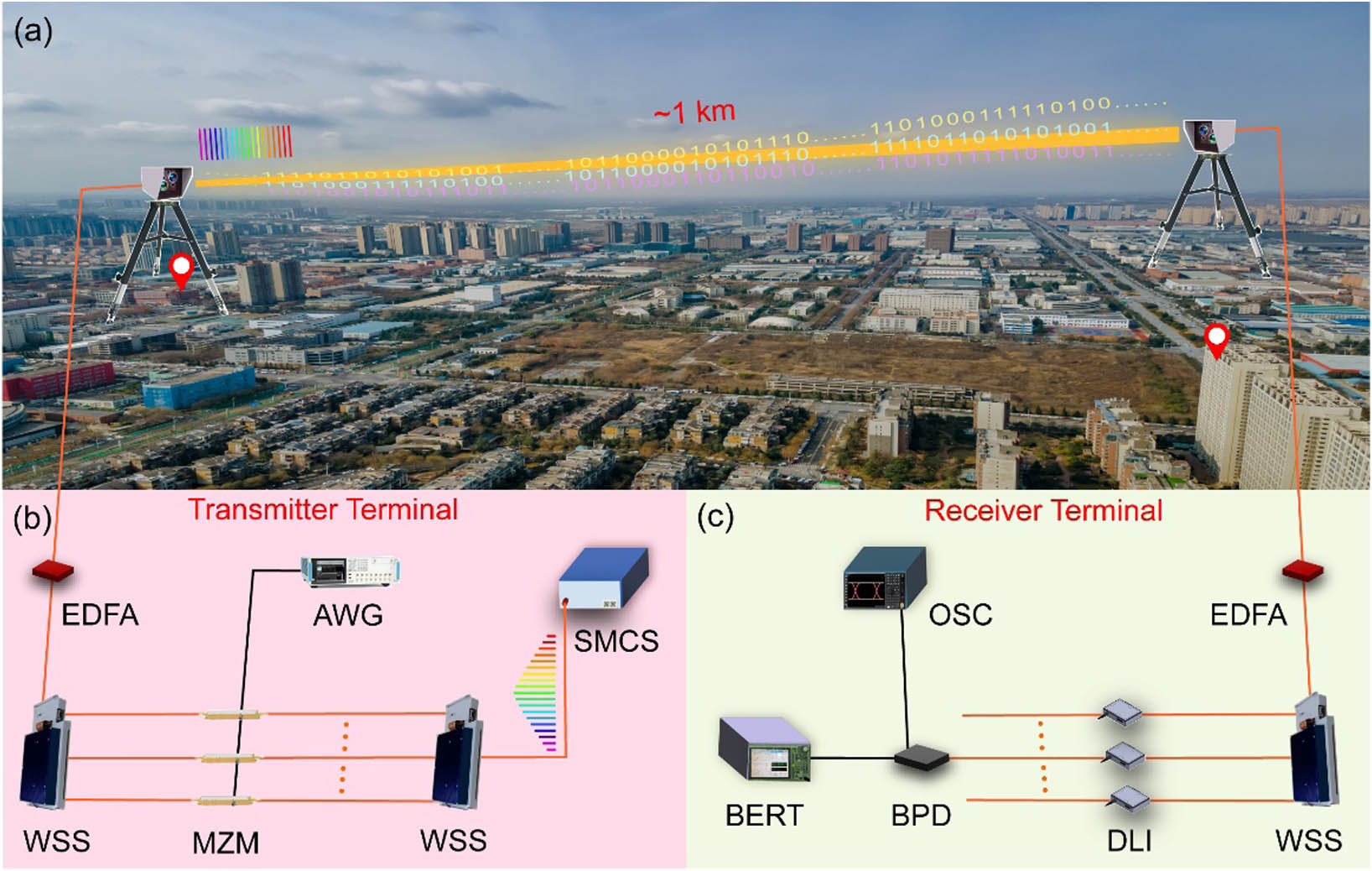
    Fig. 1. Schematic of soliton microcomb-based massively parallel FSO communication system. (a) The experiment scenario of the FSO communication system. The transmitter and receiver terminals are installed at two buildings with a straight-line distance of 1  km. The power penalty of the space link is 40  dB using two lenses with a 25 mm aperture as optical antennas. (b) The schematic diagram of the transmitter terminal. An SMC is used as a multiwavelength optical source which is demultiplexed using a commercial WSS. All the optical carriers are modulated by high-speed signals with the format of non-return-to-zero differential phase shift keying. All the optical signals are multiplexed together and amplified by an EDFA. (c) The schematic diagram of the receiver terminal. The received optical signals are demultiplexed by a WSS and demodulated using a DLI technique. SMC, soliton microcomb; WSS, wavelength selective switch; EDFA, erbium-doped fiber amplifier; MZM, Mach–Zehnder modulator; AWG, arbitrary waveform generator; DLI, delay line interferometer; BPD, balanced photodetector; OSC, oscilloscope; BERT, bit error rate tester.
    Soliton microcomb. (a) The image of a butterfly-packaged device (upper panel) and the high-index doped silica glass MRR (lower panel). (b) Optical spectrum of a single SMC with a repetition rate of ∼48.97 GHz. (c) Phase noise spectra of an individual comb line (blue) at 1560.626 nm with optical linewidth of about 500 Hz, and a continuous-wave (CW) laser (red) with optical linewidth of about 10 kHz, respectively. (d) Optical signal-to-noise ratios (OSNRs) of a comb line at the original, transmitter, and receiver terminals (the spectral resolution: 0.02 nm). The OSNR degeneration is mainly caused by the ASE of EDFAs at the transmitter and receiver terminals.
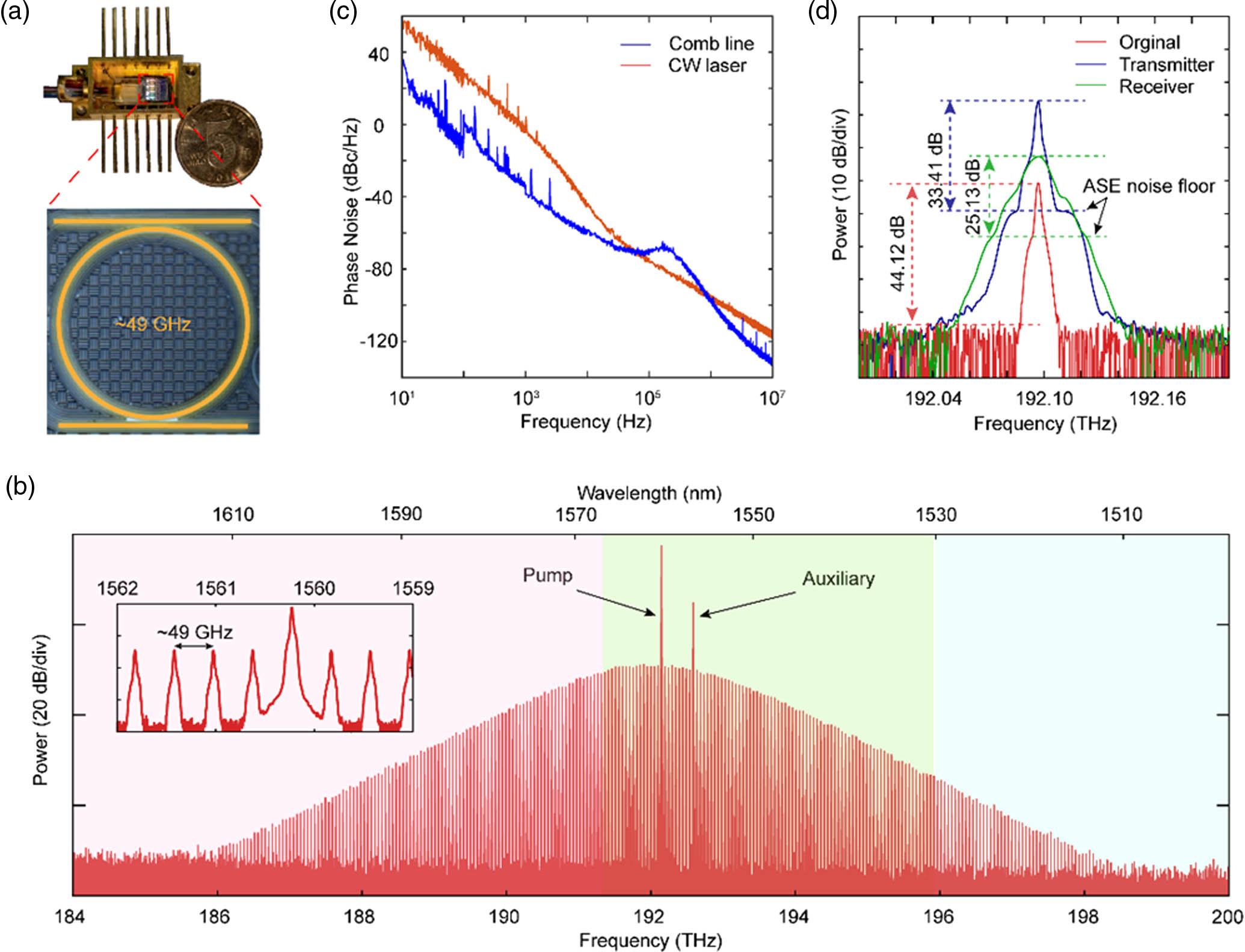
    Fig. 2. Soliton microcomb. (a) The image of a butterfly-packaged device (upper panel) and the high-index doped silica glass MRR (lower panel). (b) Optical spectrum of a single SMC with a repetition rate of 48.97  GHz. (c) Phase noise spectra of an individual comb line (blue) at 1560.626 nm with optical linewidth of about 500 Hz, and a continuous-wave (CW) laser (red) with optical linewidth of about 10 kHz, respectively. (d) Optical signal-to-noise ratios (OSNRs) of a comb line at the original, transmitter, and receiver terminals (the spectral resolution: 0.02 nm). The OSNR degeneration is mainly caused by the ASE of EDFAs at the transmitter and receiver terminals.
    Performance of the FSO communication system at 10 Gbit/s using different optical carriers. (a) Measured BER curves for different optical carriers. The dotted line shows the measured back-to-back BER curve when using a CW laser diode as the carrier. A large power penalty is induced for the FSO communication system due to the atmospheric scattering, turbulence, and background radiation, etc. (b) The influence of OSNR on BERs. The black solid line shows the theoretical BER curve versus OSNR for an ideal transmission system. Measured BER curves versus OSNR for the comb line of 1559.093 nm (blue solid line) and CW laser (red solid line) at the received power of −32 dBm. (c) Measured eye diagram at received power of −26 dBm for different optical carriers. Region vi shows the eye diagram of the recovered signal using a clock and data recovery circuit.
    Fig. 3. Performance of the FSO communication system at 10 Gbit/s using different optical carriers. (a) Measured BER curves for different optical carriers. The dotted line shows the measured back-to-back BER curve when using a CW laser diode as the carrier. A large power penalty is induced for the FSO communication system due to the atmospheric scattering, turbulence, and background radiation, etc. (b) The influence of OSNR on BERs. The black solid line shows the theoretical BER curve versus OSNR for an ideal transmission system. Measured BER curves versus OSNR for the comb line of 1559.093 nm (blue solid line) and CW laser (red solid line) at the received power of 32  dBm. (c) Measured eye diagram at received power of 26  dBm for different optical carriers. Region vi shows the eye diagram of the recovered signal using a clock and data recovery circuit.
    1.02 Tbit/s free-space data transmission using a soliton microcomb. (a) Measured BERs for 102 optical channels from 1528.726 to 1568.279 nm with transmitted power of 19.8 dBm. The BER is less than 10−9 for the optical channels in the wavelength range of 1551.586–1568.279 nm. The BER approaches 4.0×10⁻³ for the optical channels around 1530 nm, which is still lower than the threshold for hard-decision FEC with 7% overhead. The inset shows the measured real-time BER curve (red) with 10 s counting time, as well as the accumulating BER curve (green) for the comb line of 1551.192 nm. (b) The measured optical spectra of the modulated 102 optical signals after amplified and filtered at the transmitting terminal.
    Fig. 4. 1.02 Tbit/s free-space data transmission using a soliton microcomb. (a) Measured BERs for 102 optical channels from 1528.726 to 1568.279 nm with transmitted power of 19.8 dBm. The BER is less than 109 for the optical channels in the wavelength range of 1551.586–1568.279 nm. The BER approaches 4.0×10³ for the optical channels around 1530 nm, which is still lower than the threshold for hard-decision FEC with 7% overhead. The inset shows the measured real-time BER curve (red) with 10 s counting time, as well as the accumulating BER curve (green) for the comb line of 1551.192 nm. (b) The measured optical spectra of the modulated 102 optical signals after amplified and filtered at the transmitting terminal.
    Wen Shao, Yang Wang, Shuaiwei Jia, Zhuang Xie, Duorui Gao, Wei Wang, Dongquan Zhang, Peixuan Liao, Brent E. Little, Sai T. Chu, Wei Zhao, Wenfu Zhang, Weiqiang Wang, Xiaoping Xie. Terabit FSO communication based on a soliton microcomb[J]. Photonics Research, 2022, 10(12): 2802
    Download Citation