• Acta Optica Sinica
  • Vol. 39, Issue 1, 0124001 (2019)
Zhuangzhi Wei1、*, Wenrui Xue1、*, Yanling Peng1, Xin Cheng1, and Changyong Li2、3
Author Affiliations
  • 1 College of Physics and Electronic Engineering, Shanxi University, Taiyuan, Shanxi 0 30006, China
  • 2 State Key Laboratory of Quantum Optics and Quantum Optics Devices, Institute of Laser Spectroscopy, Shanxi University, Taiyuan, Shanxi 0 30006, China
  • 3 Collaborative Innovation Center of Extreme Optics, Shanxi University, Taiyuan, Shanxi 0 30006, China
  • show less
    DOI: 10.3788/AOS201939.0124001 Cite this Article Set citation alerts
    Zhuangzhi Wei, Wenrui Xue, Yanling Peng, Xin Cheng, Changyong Li. Mode Characteristics of Waveguides Based on Three Graphene-Coated Dielectric Nanowires[J]. Acta Optica Sinica, 2019, 39(1): 0124001 Copy Citation Text show less
    Cross section of waveguides based on three graphene-coated dielectric nanowires with non-coplanar axis. The black rings on the outside of the dielectric nanowires are graphene
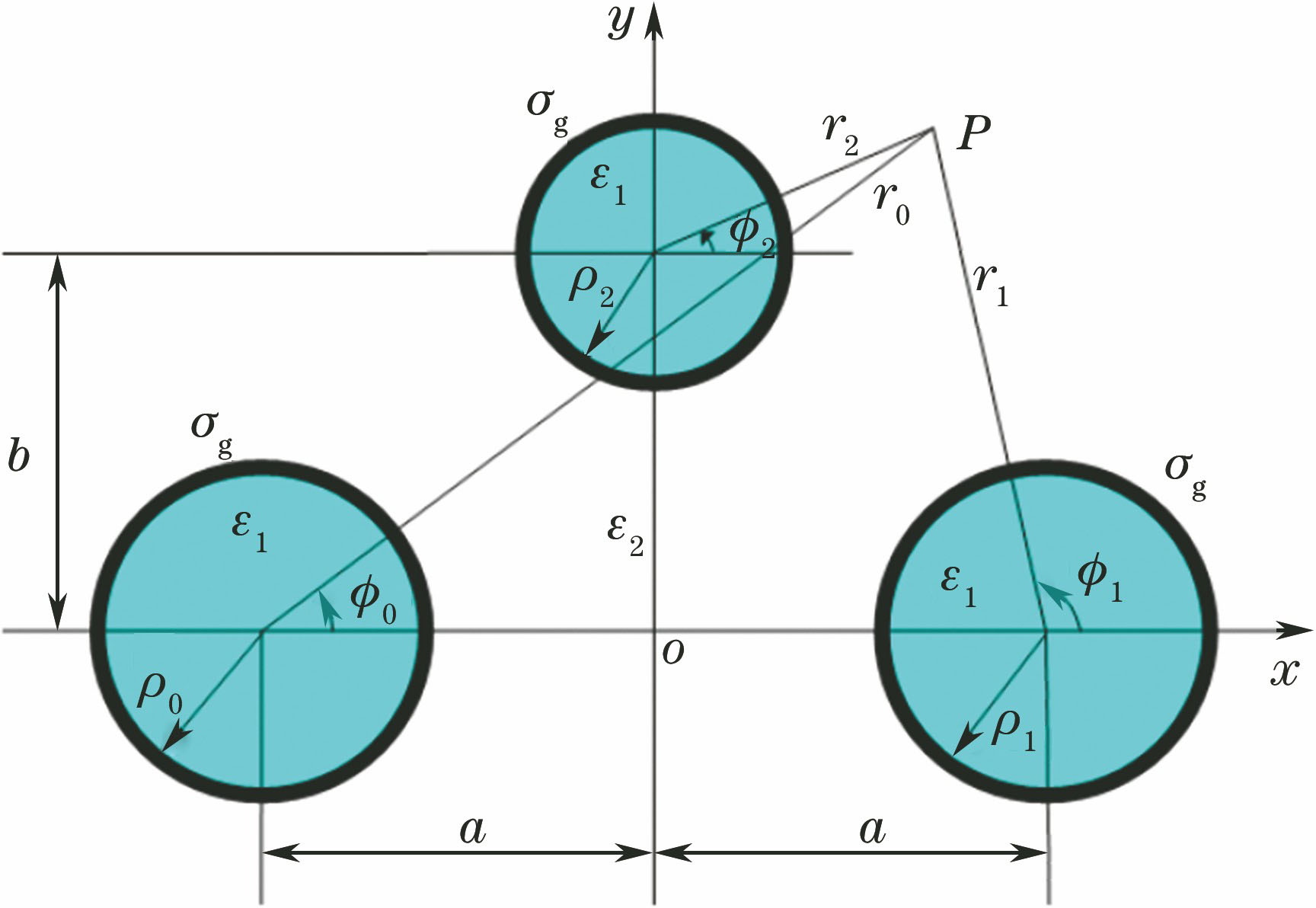
    Fig. 1. Cross section of waveguides based on three graphene-coated dielectric nanowires with non-coplanar axis. The black rings on the outside of the dielectric nanowires are graphene
    Field distributions of five modes at f=35 THz,ρ0=ρ1=100 nm,ρ2=50 nm,a=175 nm,b=60 nm, and EF=0.5 eV
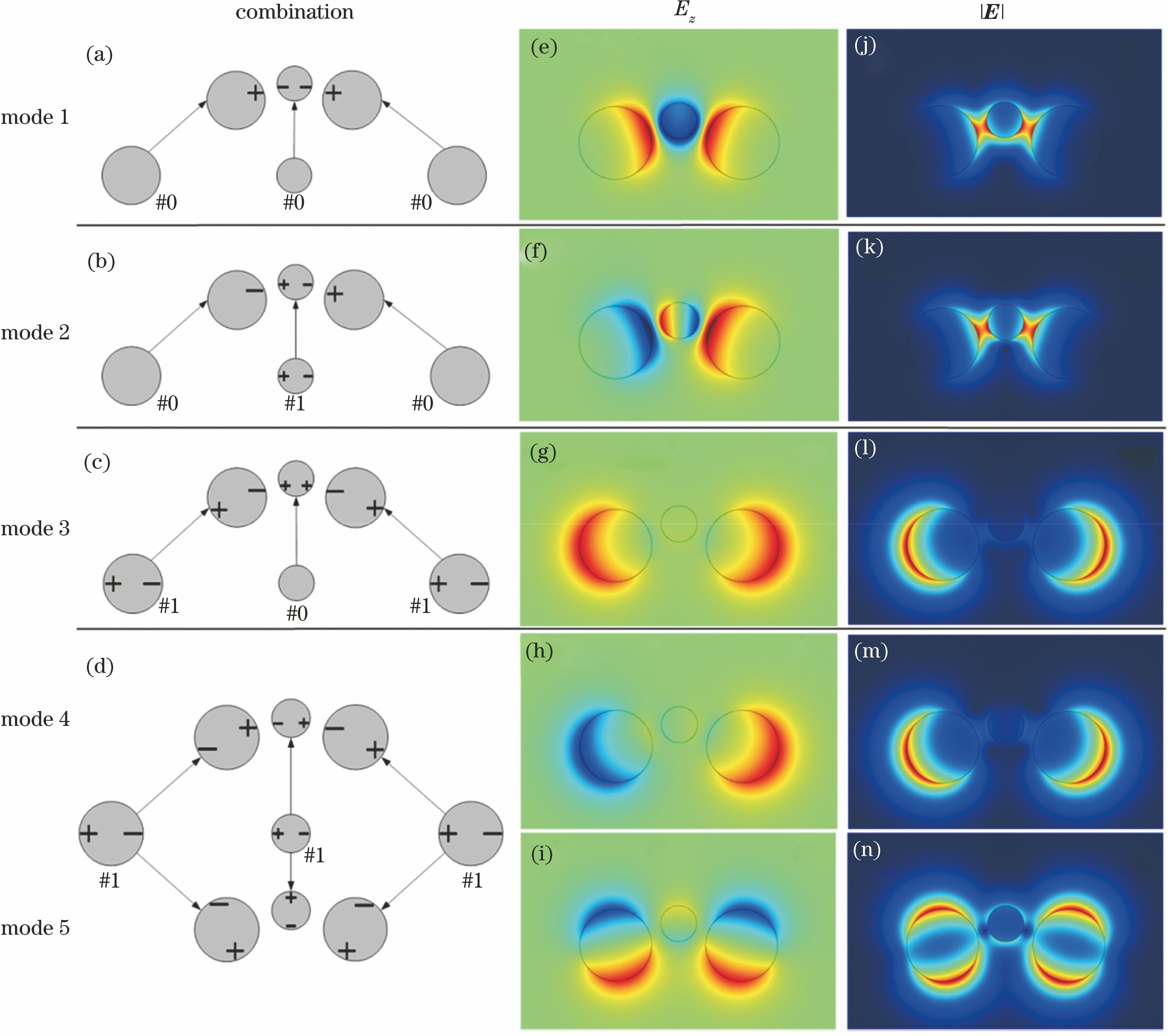
    Fig. 2. Field distributions of five modes at f=35 THz,ρ0=ρ1=100 nm,ρ2=50 nm,a=175 nm,b=60 nm, and EF=0.5 eV
    Dependency of (a) real part of the effective refractive index and (b) propagation length on the operating frequency f
    Fig. 3. Dependency of (a) real part of the effective refractive index and (b) propagation length on the operating frequency f
    Distributions of electric field of mode 1 when the operating frequency f is (a) 31 THz and (b) 39 THz at ρ0=ρ1=100 nm,ρ2=50 nm,a=175 nm,b=60 nm, and EF=0.5 eV
    Fig. 4. Distributions of electric field of mode 1 when the operating frequency f is (a) 31 THz and (b) 39 THz at ρ0=ρ1=100 nm,ρ2=50 nm,a=175 nm,b=60 nm, and EF=0.5 eV
    Dependency of (a) real part of the effective refractive index and (b) propagation length on the radius ρ2
    Fig. 5. Dependency of (a) real part of the effective refractive index and (b) propagation length on the radius ρ2
    Distributions of electric field of mode 1 when the radius ρ2 of the nanowire 2 is (a) 25 nm and (b) 55 nm at ρ0=ρ1=100 nm,f=35 THz,a=175 nm,b=60 nm, and EF=0.5 eV
    Fig. 6. Distributions of electric field of mode 1 when the radius ρ2 of the nanowire 2 is (a) 25 nm and (b) 55 nm at ρ0=ρ1=100 nm,f=35 THz,a=175 nm,b=60 nm, and EF=0.5 eV
    Dependency of (a) real part of effective refractive index and (b) propagation length on height b
    Fig. 7. Dependency of (a) real part of effective refractive index and (b) propagation length on height b
    Distributions of electric field of mode 1 when the height b is (a) 10 nm and (b) 100 nm at ρ0=ρ1=100 nm,ρ2=50 nm,f=35 THz,a=175 nm, and EF=0.5 eV
    Fig. 8. Distributions of electric field of mode 1 when the height b is (a) 10 nm and (b) 100 nm at ρ0=ρ1=100 nm,ρ2=50 nm,f=35 THz,a=175 nm, and EF=0.5 eV
    Dependency of (a) real part of effective refractive index and (b) propagation length on space a
    Fig. 9. Dependency of (a) real part of effective refractive index and (b) propagation length on space a
    Distributions of electric field of mode 1 when the space a is (a) 160 nm and (b) 195 nm at ρ0=ρ1=100 nm,ρ2=50 nm,f=35 THz,b=60 nm, and EF=0.5 eV
    Fig. 10. Distributions of electric field of mode 1 when the space a is (a) 160 nm and (b) 195 nm at ρ0=ρ1=100 nm,ρ2=50 nm,f=35 THz,b=60 nm, and EF=0.5 eV
    Dependency of (a) real part of effective refractive index and (b) propagation length on Fermi energy EF
    Fig. 11. Dependency of (a) real part of effective refractive index and (b) propagation length on Fermi energy EF
    Distributions of electric field of mode 1 when the Fermi energy EF is (a) 0.4 eV and (b) 0.8 eV at ρ0=ρ1=100 nm,ρ2=50 nm,f=35 THz,a=175 nm, and b=60 nm
    Fig. 12. Distributions of electric field of mode 1 when the Fermi energy EF is (a) 0.4 eV and (b) 0.8 eV at ρ0=ρ1=100 nm,ρ2=50 nm,f=35 THz,a=175 nm, and b=60 nm
    Comparison of propagation length of mode 1 of the waveguide with coplanar axis and the waveguide with non-coplanar axis. (a) Frequency; (b) radius of the middle nanowire; (c) distance between two nanowires in the horizontal direction; (d) Fermi energy
    Fig. 13. Comparison of propagation length of mode 1 of the waveguide with coplanar axis and the waveguide with non-coplanar axis. (a) Frequency; (b) radius of the middle nanowire; (c) distance between two nanowires in the horizontal direction; (d) Fermi energy
    Electric field distribution of (a) waveguide with coplanar axis and (b) waveguide with non-coplanar axis when ρ2=40 nm
    Fig. 14. Electric field distribution of (a) waveguide with coplanar axis and (b) waveguide with non-coplanar axis when ρ2=40 nm
    Zhuangzhi Wei, Wenrui Xue, Yanling Peng, Xin Cheng, Changyong Li. Mode Characteristics of Waveguides Based on Three Graphene-Coated Dielectric Nanowires[J]. Acta Optica Sinica, 2019, 39(1): 0124001
    Download Citation