
Yaqin Hao, Yuan Yao, Haosen Shi, Hongfu Yu, Yanyi Jiang, Longsheng Ma, "Frequency control of a lattice laser at 759 nm by referencing to Yb clock transition at 578 nm," Chin. Opt. Lett. 20, 120201 (2022)
- Chinese Optics Letters
- Vol. 20, Issue 12, 120201 (2022)
Abstract
1. Introduction
In the last decade, tremendous progress in optical atomic clocks has been made: the frequency instability and uncertainty of optical atomic clocks have reached
Compared with single ion optical clocks, optical lattice clocks based on thousands of neutral atoms have much lower quantum projection noise-limited frequency instability due to a larger atom number[1,4]. An optical lattice is employed to confine neutral atoms in the Lamb–Dick regime, which removes the first-order Doppler shift and the photon recoil shift[9], and thus it allows Doppler-free high spectral resolution. However, the strong electric field of the lattice light will induce non-ignorable Stark shifts in both the lower and upper states of the clock transition. To cancel the light shifts, the frequency of the lattice light must be stabilized at a specific wavelength, named the magic wavelength[10–14].
Reference cavities made of ultralow expansion (ULE) glass are commonly employed to stabilize the frequency of lattice lasers[11,14,15]. Since the length of reference cavities changes due to temperature fluctuation and aging, the frequency of these cavity-stabilized lattice lasers drifts typically on the order of 10–100 kHz in a day, even the temperature of the reference cavities is stabilized with a fluctuation less than 10 mK. In an alternative method, transfer cavities referenced to atomic transitions are used to stabilize the frequency of lattice lasers, and the long-term frequency fluctuations of the lattice lasers are on the order of the megahertz (MHz) level, limited by the fluctuations of cavity dispersion[16]. In the above two methods, additional optical cavities are employed. In order to reduce the Stark shift induced by lattice light to an uncertainty of
Sign up for Chinese Optics Letters TOC. Get the latest issue of Chinese Optics Letters delivered right to you!Sign up now
Optical frequency combs are powerful tools for measuring and controlling optical frequencies[17,18], which makes them irreplaceable in applications of optical clocks, such as frequency comparison between optical atomic clocks based on different species and absolute frequency measurement relative to cesium primary standards. Using an optical frequency comb, Bothwell et al. stabilized the frequency of the lattice light to a clock laser[12], whose frequency is resonant on the transition of Sr atoms. Therefore, the frequency of the lattice laser is traceable to the Sr optical clock, and the laser frequency calibration is not necessary. In this method, there is no extra optical cavity. However, the optical frequency comb is required to be tightly locked on the clock laser to achieve narrow-linewidth comb lines, which is a challenge for long-time operation.
Although optical combs frequency-stabilized to microwave standards are more robust, and their continuous operation time is longer[19], the frequency noise of such combs is much higher, compared to those stabilized to a narrow-linewidth laser. To overcome this problem, Pizzocaro et al. employed a Ti:sapphire laser with a linewidth of 20 kHz as the lattice laser, whose frequency is monitored for compensating the slow frequency drift via an optical frequency comb referenced on a hydrogen maser[20]. For another, with the transfer oscillator scheme and self-referenced time base, we have realized high precision frequency transfer from a narrow-linewidth laser to a free-running laser without degrading the laser coherence even by using an optical frequency comb frequency-stabilized to a rubidium (Rb) clock[21].
In this work, we apply such a technique to realize the frequency control of a lattice laser at 759 nm. The 759 nm laser is referenced to a clock laser at 578 nm of an ytterbium (Yb) optical clock via an optical frequency comb as a transfer oscillator. The optical frequency comb is frequency-stabilized to a commercial Rb clock for long-term continuous operation. Although the frequency noise of the comb tooth (
2. Experimental Setup
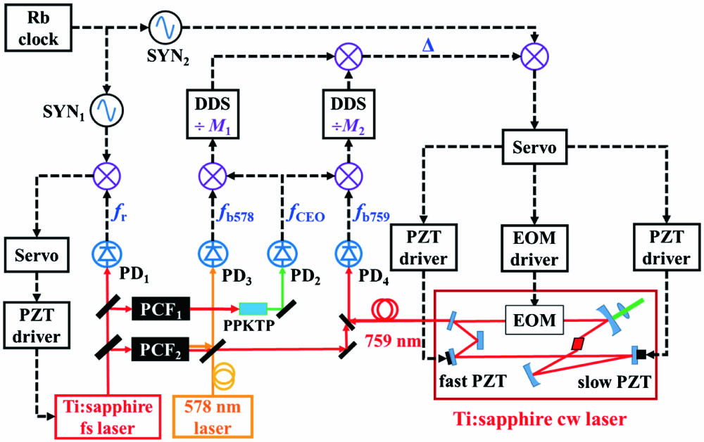
The experimental setup of frequency control of the lattice laser at 759 nm is shown in Fig. 1. The 759 nm laser is a Ti:sapphire continuous wave (cw) laser pumped by a laser at 532 nm (Matisse, Spectra-Physics). The output power is more than 1 W, and the linewidth is less than 1 MHz. A small part of the light beam with a power of 10 mW is sent to an optical frequency comb for frequency control via a piece of optical fiber without fiber noise cancellation.
![]()
Figure 1.Experimental set-up for frequency control of the 759 nm laser. The solid lines represent the light path, while the dashed lines represent the electrical path. Ti:sapphire fs laser, Ti:sapphire femtosecond laser; PCF, photonic crystal fiber; PPKTP, periodically poled KTiOPO4; DDS, direct digital synthesizer; EOM, electro-optic modulator; PZT, piezo-transducer; Ti:sapphire cw laser, Ti:sapphire continuous wave laser; PD, photo detector; SYN, RF synthesizer.
A Ti:sapphire mode-locked femtosecond (fs) laser operates with an average output power of 1.8 W and a repetition rate (
The output of
These signals are then sent to two DDSs with divisors
The outputs of the DDSs are mixed in a DBM to subtract the frequency noise of
By phase locking
We employ the frequency-locked laser at 759 nm as the lattice laser in an Yb optical clock. As shown in Fig. 2(a), a large part of the 759 nm laser is coupled into a piece of polarization maintenance (PM) optical fiber. The light output from the optical fiber is focused by a lens, and it is reflected by a dichroic curved mirror to build up an optical lattice with a trap depth of
![]()
Figure 2.(a) Simplified experimental set-up for optical clock operation. (b) Rabi spectrum with a probe time of 200 ms.
Cooling and trapping of Yb atoms are performed through a two-stage magneto-optical trap (MOT) using a strong transition of
Based on the above spectra with a linewidth of
3. Results
To evaluate the frequency instability induced by the transfer process, the frequency of
![]()
Figure 3.Frequency noise induced by a 10-m-long fiber (red dots) and in-loop frequency noise during frequency transfer (black squares).
The frequency accuracy of the lattice laser is also evaluated. According to Eq. (7), the frequency of the 759 nm laser is dependent on the divisors of the DDSs,
Since
![]()
Figure 4.(a) Timing sequence of self-comparison. Blue and purple lines indicate two independent stabilizations. (b) Scalar lattice shift at U = 200Er measured by interleaving between a trap depth of 158(4)Er and 226(4)Er at different lattice frequencies.
4. Conclusion
We report a frequency-controlled lattice laser at 759 nm by referencing to a clock laser at 578 nm via an optical frequency comb stabilized to a Rb clock. The frequency instability of the lattice laser is on the order of
References
[1] E. Oelker, R. B. Huston, C. J. Kennedy, L. Sonderhouse, T. Bothwell, A. Goban, D. Kedar, C. Sanner, J. M. Robinson, G. E. Marti, D. G. Matei, T. Legero, M. Giunta, R. Holzwarth, F. Riehle, U. Sterr, J. Ye. Demonstration of 4.8 × 10⁻¹⁷ stability at 1 s for two independent optical clocks. Nat. Photon., 13, 714(2019).
[2] N. Huntemann, C. Sanner, B. Lipphardt, C. Tamm, E. Peik. Single-ion atomic clock with 3 × 10⁻¹⁸ systematic uncertainty. Phys. Rev. Lett., 116, 063001(2016).
[3] S. M. Brewer, J. S. Chen, A. M. Hankin, E. R. Clements, C. W. Chou, D. J. Wineland, D. B. Hume, D. R. Leibrandt. 27Al+ quantum-logic clock with a systematic uncertainty below 10−18. Phys. Rev. Lett., 123, 033201(2019).
[4] W. F. McGrew, X. Zhang, R. J. Fasano, S. A. Schäffer, K. Beloy, D. Nicolodi, R. C. Brown, N. Hinkley, G. Milani, M. Schioppo, T. H. Yoon, A. D. Ludlow. Atomic clock performance enabling geodesy below the centimetre level. Nature, 564, 87(2018).
[5] M. S. Safronova, D. Budker, D. DeMille, D. F. J. Kimball, A. Derevianko, C. W. Clark. Search for new physics with atoms and molecules. Rev. Mod. Phys., 90, 025008(2018).
[6] C. Sanner, N. Huntemann, R. Lange, C. Tamm, E. Peik, M. S. Safronova, S. G. Porsev. Optical clock comparison for Lorentz symmetry testing. Nature, 567, 204(2019).
[7] S. Kolkowitz, I. Pikovski, N. Langellier, M. D. Lukin, R. L. Walsworth, J. Ye. Gravitational wave detection with optical lattice atomic clocks. Phys. Rev. D, 94, 124043(2016).
[8] B. M. Roberts, G. Blewitt, C. Dailey, M. Murphy, M. Pospelov, A. Rollings, J. Sherman, W. Williams, A. Derevianko. Search for domain wall dark matter with atomic clocks on board global positioning system satellites. Nat. Commun., 8, 1195(2017).
[9] C. I. Westbrook, R. N. Watts, C. E. Tanner, S. L. Rolston, W. D. Phillips, P. D. Lett, P. L. Gould. Localization of atoms in a three-dimensional standing wave. Phys. Rev. Lett., 65, 33(1990).
[10] T. Ido, H. Katori. Recoil-free spectroscopy of neutral Sr atoms in the Lamb-Dicke regime. Phys. Rev. Lett., 91, 053001(2003).
[11] I. Ushijima, M. Takamoto, H. Katori. Operational magic intensity for Sr optical latice clock. Phys. Rev. Lett., 121, 263202(2018).
[12] T. Bothwell, D. Kedar, E. Oelker, J. M. Robinson, S. L. Bromley, W. L. Tew, J. Ye, C. J. Kennedy. SrI optical lattice clock with uncertainty of 2×10⁻¹⁸. Metrologia, 56, 065004(2019).
[13] M. J. Zhang, H. Liu, X. Zhang, K. L. Jiang, Z. X. Xiong, B. L. Lu, L. X. He. Hertz-level clock spectroscopy of 171Yb atoms in a one-dimensional optical lattice. Chin. Phys. Lett., 33, 070601(2016).
[14] R. C. Brown, N. B. Phillips, K. Beloy, W. F. McGrew, M. Schioppo, R. J. Fasano, G. Milani, X. Zhang, N. Hinkley, H. Leopardi, T. H. Yoon, D. Nicolodi, T. M. Fortier, A. D. Ludlow. Hyperpolarizability and operational magic wavelength in an optical lattice clock. Phys. Rev. Lett., 119, 253001(2017).
[15] Q. Gao, M. Zhou, C. Y. Han, S. Y. Li, S. Zhang, Y. Yao, B. Li, H. Qiao, D. Ai, G. Lou, M. Y. Zhang, Y. Y. Jiang, Z. Y. Bi, L. S. Ma, X. Y. Xu. Systematic evaluation of a 171Yb optical clock by synchronous comparison between two lattice systems. Sci. Rep., 8, 8022(2018).
[16] P. G. Westergaard, J. Lodewyck, L. Lorini, A. Lecallier, E. A. Burt, M. Zawada, J. Millo, P. Lemonde. Lattice-induced frequency shifts in Sr optical lattice clocks at the 10-17 level. Phys. Rev. Lett., 106, 210801(2011).
[17] J. L. Hall. Nobel lecture: defining and measuring optical frequencies. Rev. Mod. Phys., 78, 1279(2006).
[18] T. W. Hänsch. Nobel lecture: passion for precision. Rev. Mod. Phys., 78, 1297(2006).
[19] G. Yang, H. S. Shi, Y. Yao, H. F. Yu, Y. Y. Jiang, A. Bartels, L. S. Ma. Long-term frequency-stabilized optical frequency comb based on a turnkey Ti:sapphire mode-locked laser. Chin. Opt. Lett., 19, 121405(2021).
[20] M. Pizzocaro, P. Thoumany, B. Rauf, F. Bregolin, G. Milani, C. Clivati, G. A. Costanzo, F. Levi, D. Calonico. Absolute frequency measurement of the 1S0–3P0 transition of 171Yb. Metrologia, 54, 102(2017).
[21] Y. Yao, B. Li, G. Yang, X. T. Chen, Y. Q. Hao, H. F. Yu, Y. Y. Jiang, L. S. Ma. Optical frequency synthesizer referenced to an ytterbium optical clock. Photon. Res., 9, 98(2021).
[22] L. Jin, Y. Y. Jiang, Y. Yao, H. F. Yu, Z. Y. Bi, L. S. Ma. Laser frequency instability of 2 × 10⁻¹⁶ by stabilizing to 30-cm-long Fabry-Perot cavities at 578 nm. Opt. Express, 26, 18699(2018).
[23] Y. Y. Jiang, Z. Y. Bi, R. Lennart, L. S. Ma. A collinear self-referencing set-up for control of the carrier-envelope offset frequency in Ti:sapphire femtosecond laser frequency combs. Metrologia, 42, 304(2005).
[24] H. R. Telle, B. Lipphardt, J. Stenger. Kerr-lens, mode-locked lasers as transfer oscillators for optical frequency measurements. Appl. Phys. B, 74, 1(2002).
[25] W. Nagourney, J. Sandberg, H. Dehmelt. Shelved optical electron amplifier: observation of quantum jumps. Phys. Rev. Lett., 56, 2797(1986).
[26] Y. X. Sun, Y. Yao, Y. Q. Hao, H. F. Yu, Y. Y. Jiang, L. S. Ma. Laser stabilizing to ytterbium clock transition with Rabi and Ramsey spectroscopy. Chin. Opt. Lett., 18, 070201(2020).
[27] Y. Y. Jiang, A. D. Ludlow, N. D. Lemke, R. W. Fox, J. A. Sherman, L. S. Ma, C. W. Oates. Making optical atomic clocks more stable with 10−16-level laser stabilization. Nat. Photon., 5, 158(2011).
[28] T. L. Nicholson, M. J. Martin, J. R. Williams, B. J. Bloom, M. Bishof, M. D. Swallows, S. L. Campbell, J. Ye. Comparison of two independent Sr optical clocks with 1 × 10⁻¹⁷ stability at 103 s. Phys. Rev. Lett., 109, 230801(2012).
[29] Q. Wang, Y. G. Lin, F. Meng, Y. Li, B. K. Lin, E. J. Zang, T. C. Li, Z. J. Fang. Magic wavelength measurement of the 87Sr optical lattice clock at NIM. Chin. Phys. Lett., 33, 103201(2016).


Set citation alerts for the article
Please enter your email address

© Copyright 2018-2021 | Chinese Laser Press. All Rights Reserved 沪ICP备15018463号-20