Abstract
The nonreciprocal circular dichroism and Faraday rotation effect for terahertz (THz) waves in longitudinally magnetized InSb were investigated by theoretical and experimental studies in the THz regime, which indicated its ability for a THz circularly polarized isolator, THz circular polarizer, tunable polarization converter, and polarization modulator by manipulation of different magnetic fields. Furthermore, we demonstrated the InSb plasmonics based on its magneto-optical effects combined with artificial microstructure. We found the magneto-optical enhancement mechanisms in this magneto-plasmonic structure, achieving broadband near-perfect orthogonal linear polarization conversion modulated by the weak magnetic field in an experiment with an extinction ratio of 33 dB. Moreover, the magneto-optical modulation with an amplitude modulation depth of 95.8% can be achieved by this device under a weak magnetic field of 150 mT. InSb and its magneto-plasmonic device have broad potential for a THz isolator, magneto-optical modulator, and polarization convertor in THz application systems.1. INTRODUCTION
Terahertz (THz) radiation is electromagnetic radiation whose frequency lies from 0.1 THz to 10 THz between the microwave and infrared regions of the spectrum [1]. With greatly successful progress in THz science and technology, THz sources [2], detection [3], control [4,5], and application [6,7] by means of mainly electrical methods are developing rapidly. For further development of the THz application system, there is a high demand for efficient devices for guiding, modulating, and manipulating the THz wave in its amplitude, phase, and polarization [8–10]. However, research on the magnetic properties of THz waves seriously lags behind. The unique nonreciprocal effect and magnetic tunability of a magneto-optical (MO) device make it play an irreplaceable role in a high-performance isolator [11], polarization controller [12], MO modulator [13], and magnetic field sensor [14], so it is necessary to fill the “THz gap” by not only electrical but also magnetic means. Due to the lack of high-performance THz MO materials and the limitation of device fabrication, improvement in THz MO devices is still in challenge.
As a classic longitudinal MO effect (i.e., the external magnetic field direction is parallel to the direction of light propagation, called the Faraday configuration), the Faraday effect can lead to nonreciprocal rotation of the linearly polarized (LP) light in MO materials, which can be widely used as a polarization rotator, isolator, and MO modulator, if a large Faraday rotation angle can be achieved. In 2013, Shalaby et al. [15] presented the first THz isolator based on the traditional Faraday rotation effect in a bulk permanent magnet at room temperature, of which performance was very limited by the large loss of the magnet. They also demonstrated the low-loss Faraday rotation effect in the liquid of ferromagnetic nanoparticles under the weak magnetic field in the THz regime, but this rotation was very weak [16,17]. Shuvaev et al. [18] observed the first giant Faraday effect in the THz regime on epitaxial HgTe thin films at room temperature. The maximum Faraday rotation reached 0.25 rad at 0.35 THz with 70 nm thickness when , which corresponded to a large Verdet constant . Fallahi and Perruisseau-Carrier [19] also presented a graphene metasurface to manipulate giant Faraday rotation in the THz regime, of which rotation reached 0.1 rad with a broad bandwidth of over 1 THz, and this operating frequency band can be broadly tuned from 0.5 THz to 5 THz by different magnetic fields from 1 T to 7 T. In 2016, Tamagnone et al. [20] reported a THz isolator based on graphene under a strong biased magnetic field of 7 T, which exhibited isolation of about 20 dB but insertion loss of 7.5 dB at 2.9 THz. Then, Poumirol et al. [21] showed the magnetic circular dichroism and Faraday rotation in continuous and patterned graphene at 250 K and 7 T. Although these materials have great Verdet constants, the Faraday rotation angle is limited due to their thin thicknesses relative to the THz wavelength, which also requires an extremely high magnetic field and low temperature.
As a high-mobility narrow-gap semiconductor, InSb shows strong dependences on both temperature and magnetic field in the range from infrared to microwave, so this material has also been widely of interest in THz tunable devices, especially in many theoretical designs [22–25]. However, some experiment reports show that the gyroelectric MO effects of InSb are strong but far more complex than theoretical designs in the THz regime under a relatively low magnetic field. For example, Wang et al. [26] experimentally observed an interference-induced transparency effect in InSb and the magneto-plasmonic split of left and right circularly polarized modes in the Faraday configuration. In 2017, Chochol et al. [27] reported experimental demonstration of a THz magneto-plasmon polariton at the InSb–dielectric interface with a shifting of the resonance position by more than 100 GHz for the magnetic field of 0.25 T. Recently, Lin et al. [28] reported a nonreciprocal THz reflection of magneto plasmas in InSb with the Voigt configuration (i.e., transverse magnetic MO effect). This one-way mirror achieved 35 dB of isolation performance with insertion loss under only 0.2 T. However, to our knowledge, there has still been a lack of reports on the longitudinal MO effect of InSb in the THz regime, especially experimental support. In our previous works, we reported a series of THz nonreciprocal devices with magneto-plasmonic [29] and magneto-metasurface [30] structures composed of InSb, which achieved a very high isolation ratio of over 40 dB and a low insertion loss of less than 2 dB, but these were mainly in theoretical and simulative works. More clear and systemic investigations should be done to develop THz MO devices and applications based on InSb.
Sign up for Photonics Research TOC. Get the latest issue of Photonics Research delivered right to you!Sign up now
In this paper, we first investigated temperature dependence of the carrier in InSb, and then systematically studied longitudinal MO effects of magnetized InSb as a Faraday configuration in the THz regime, in both theory and experiments. The nonreciprocal circular dichroism in the cyclotron resonance band and Faraday rotation effect in the higher frequency band were confirmed. Moreover, we further demonstrated that an InSb plasmonics combined its MO effects with an artificial microstructure, in which we found MO enhancement mechanisms, achieving broadband near-perfect orthogonal linear polarization conversion modulated by the weak magnetic field in the experiment.
2. THEORY OF TERAHERTZ MAGNETO-OPTIC EFFECTS IN InSb
The dielectric properties of InSb in the THz band can be described by the Drude model when there is no magnetic field applied: where is the high-frequency limit permittivity; is the circular frequency of the THz wave; is the collision frequency of carriers; ; and is the carrier mobility, which is a function of the temperature modeled as [26,31,32]. is the plasma frequency written as , where is the electron charge, is the free-space permittivity, is the effective mass of the carrier, , and is the mass of an electron. is the phonon contribution to the dielectric function, where and are, respectively, the transverse and longitudinal optical phonon frequencies, and is the phonon-damping rate. , , and in the following calculations [28].
The carrier density can be expressed as [33] where is the Boltzmann constant, and is the intrinsic doping carrier density at 0 K. We find that the dielectric properties of InSb have strong dispersion in the THz range and are closely related to the carrier density , which is strongly dependent on the temperature described by Eq. (2), as shown in Fig. 1(a). remains the initial doping density when and shows an exponential rise when .
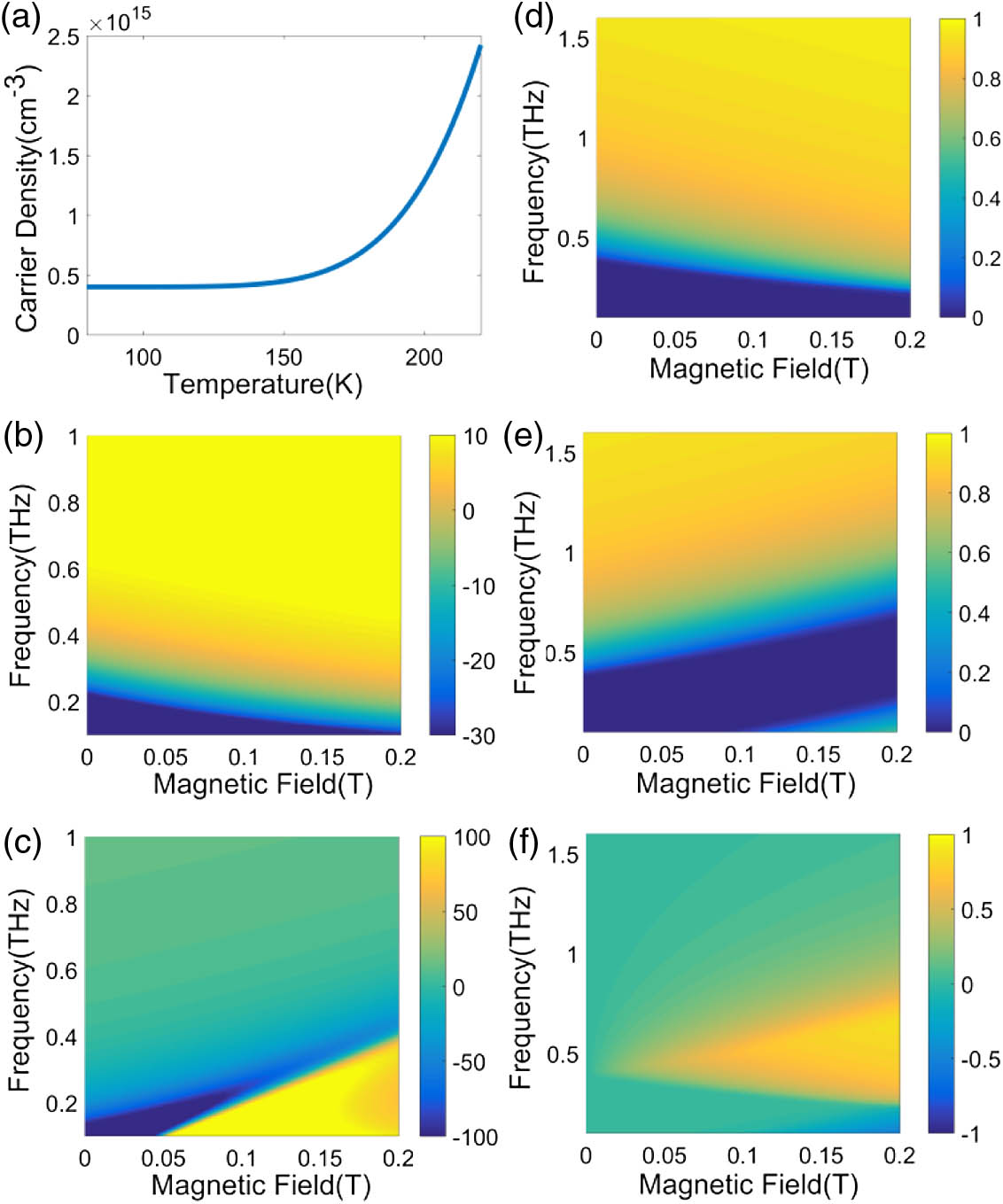
Figure 1.(a) Simulative carrier density of InSb at different temperatures; maps of the real part of (b) and (c) of longitudinally magnetized InSb in the THz regime under different magnetic fields from 0 T to 0.2 T; maps of theoretical transmittance (d) and (e) of longitudinally magnetized InSb in the THz regime under different magnetic fields from 0 T to 0.2 T; (f) map of the theoretical transmittance difference between the LCP and the RCP ().
When a magnetic field is applied in a specific direction, the cyclotron motion of the carriers in InSb is performed along the direction of the magnetic field, and the cyclotron frequency , where is the magnetic flux density. When the directions of both the THz wave propagation and magnetic field are parallel along the direction in InSb, we call it a Faraday configuration, and the wave equation can be written in the following form [34]: where the elements of the tensor can be expressed as Two circularly polarized eigenwaves can be solved from Eq. (3). The eigenwave of represents the counterclockwise rotation wave (CCW), also called the left-handed circularly polarized wave (LCP), along the axis with its permittivity of . On the contrary, the eigenwave of represents the clockwise rotation wave (CW), also called the right-handed circularly polarized wave (RCP), along the axis with its permittivity of . If the direction of the magnetic field is unchanged, the properties of these two eigenwaves are related only to the rotation directions (counterclockwise and clockwise rotations in the plane), regardless of the wave propagation direction.
According to the above formula, we calculate and in the THz regime under a different magnetic field at 80 K, as shown in Figs. 1(b) and 1(c). We find that the contributions of free carriers to the dielectric dispersion are much larger than those of the phonons in our case. The influence of the term in Eq. (4) is almost negligible on the results in Fig. 1. shows a Drude lineshape. The frequency point of is defined as the effective plasma frequency of the LCP, expressed as . When , the magnetized InSb shows the metallic character of the LCP, which is quickly attenuated and reflected in the magnetized InSb. When , the magnetized InSb shows the dielectric character of the LCP and it can propagate through the InSb. As the magnetic field increases, moves to a lower frequency, as shown in Fig. 1(b).
Figure 1(c) shows that has a singularity at with a strong gyrotropic resonance as a Drude–Lorentzian lineshape. This is the first point of . The second frequency point of at a higher frequency is defined as the effective plasma frequency of the RCP as follows: . There is a frequency band that when . When , the RCP can propagate through the InSb, but the frequency band of is a forbidden band for the RCP. As the magnetic field increases, as shown in Fig. 1(c), increases accordingly, so the position of the forbidden band moves to a higher frequency.
Since is always larger than , when , , so the typical Faraday rotation effect can be obtained. But when , the nonreciprocal circular dichroism can be obtained. For instance, when an LP wave is incident into the magnetized InSb along , the LCP component can pass through the InSb, but the RCP component is totally forbidden in the band of , so the output wave is an LCP. When the incident wave is the LCP in the band of , it can pass through the InSb along , but cannot pass back along . The RCP is just the opposite. Therefore, the nonreciprocal one-way transmission for the LCP and RCP waves can be achieved in the longitudinally magnetized InSb.
Furthermore, we calculated the theoretical transmission of the InSb layer for the LCP without considering interface reflection and interference, expressed as , where is the extinction coefficient, is the speed of light in vacuum, and is the thickness of the InSb crystal. The formula for for the RCP has the same form as . Both of them are shown in Figs. 1(d) and 1(e), respectively. We find that both the LCP and RCP can pass InSb above 0.5 THz and be quickly attenuated and reflected at less than 0.5 THz when . But it is different in that as the magnetic field increases, the boundary has a completely different trend. We find a region that permits the LCP but forbids the RCP, so we calculate , as shown in Fig. 1(f). The yellow region in Fig. 1(f) indicates the nonreciprocal one-way transmission of InSb for the THz circularly polarized waves. The increase in the magnetic field can significantly increase the bandwidth of the circular dichroic region.
3. THz MAGNETO-OPTICAL POLARIZATION CONVERSION IN InSb CRYSTAL
We do our experiment by using a THz time domain spectroscopy (THz-TDS) system with cryogenic magnetic field equipment, as shown in Fig. 2. A THz pulse is generated by a low-temperature-grown GaAs photoconductive antenna (PCA), and the other PCA is used for THz detection. The excitation source is a Ti:sapphire laser with 75 fs duration of 80 MHz repetition rate at 800 nm. The cryogenic Dewar flask can control the temperature from 78 K to 400 K by adding liquid nitrogen. All the experiments are carried out at room temperature with humidity of less than 5%. The InSb sample is placed in the center of the sample cell of the Dewar flask. The InSb used in our experiment is 500 μm thick n-doped single crystal by the epitaxial growth with a carrier density of at 100 K and mobility of at 273 K.

Figure 2.(a) Schematic diagram of experimental THz-MOS system; (b) photo of the experimental equipment.
First, we investigated the thermal tunability of InSb without a magnetic field in the low-temperature range. Figure 3(a) shows the measured THz signal of InSb with temperature increasing from 80 K to 200 K, which demonstrated that the signal pulses slightly moved forward and their amplitudes dropped down with the increase in temperature. The transmission spectra were obtained by Fourier transform of the time domain signals with reference to the blank sample cell without InSb crystal, as shown in Fig. 3(b). We observed that the THz transmission of InSb displayed high-pass filtering characteristics: THz waves are forbidden to propagate through InSb in the low-frequency band, but its transmittance dramatically rises when the frequency is larger than a certain frequency point, which is called the cutting frequency . As the temperature rises, gradually shifts to a higher frequency range, as shown in Figs. 3(b) and 3(c). To confirm the experimental results and more clearly understand the carrier changes of InSb with the temperature, we simulate the transmission spectra of 500 μm thick InSb by the finite-difference time domain (FDTD) method, as shown in Fig. 3(d). The parameters of InSb in the Drude model used in the simulation are all derived from the parameter data and Eqs. (1) and (2) in Section 2. We can see the simulation results in Fig. 3(d) are in good agreement with the experimental results in Fig. 3(b). Cutting frequency is related just to plasmon frequency , so the carrier changes in the experiment also fit well with the theoretical calculation expressed by Eq. (2) in Fig. 1(a) and numerical simulation in Fig. 3(c). Therefore, these results indicate good tunable THz high-pass filtering characteristics by controlling the temperature of InSb.
Figure 3.Experimental and simulated results of InSb with different temperatures: (a) measured THz time domain pulses; (b) experimental intensity transmission expressed in dB; (c) simulated carrier density and cutting frequency ; (d) simulated transmission.
Next, we investigated the THz Faraday MO property of InSb crystal under a longitudinal magnetic field. As shown in Figs. 2 and 4(a), a pair of tunable hollow ring magnets is attached to the two sides of the sample cell of a Dewar flask to apply the longitudinal magnetic field from 0 T to 0.17 T. A rotatable THz polarizer is placed in front of the THz detector to measure the two orthogonal LP components of the magnetized InSb sample. The whole equipment forms a THz MO spectroscopy (THz-MOS) system to measure THz transmission spectra, phase spectra, and arbitrary polarization states of materials at different external magnetic fields and temperatures.
Figure 4.Experimental results of InSb under magnetic field: (a) schematic diagram of the experimental configuration; (b) experimental time domain pulses in two orthogonal directions under magnetic fields of 150 mT and 0 mT; (c) experimental transmission of LCP and RCP components; (d) experimental Faraday rotation angles under different magnetic fields.
We can rotate the THz polarizer at 45° and in THz-MOS to detect 45° and LP components passing through magnetized InSb. Figure 4(b) shows the THz time domain pulses of 45° and LP components under a magnetic field of 0 mT and 150 mT at 80 K. Without a magnetic field, the 45° and LP components are the same, which means the polarization state has no change in the incident wave. There are some differences between these two signals when there is a magnetic field applied, indicating that the THz polarization state has been changed after passing through the InSb. The amplitude [ and ] and phase [ and ] of them can be obtained by a Fourier transform of the time domain signals. In the Faraday configuration, the eigenmodes of light in InSb are an LCP and an RCP, so the two measured orthogonal LP components should be converted as forms of the orthogonal LCP and RCP components; the transmission spectra of the LCP and RCP can be expressed as follows: We find that the LCP is much higher than the RCP in the lower frequency band around the cyclotron resonance range marked by the yellow color. From 0.4 THz to 0.8 THz, the LCP component can transmit through InSb but the RCP is forbidden, which means a nonreciprocal circular dichroism effect or nonreciprocal one-way transmission for the circularly polarized light is realized in this frequency range. The isolation spectrum between the LCP and RCP is also shown in Fig. 4(c); maximum isolation reaches 20 dB, and the 10 dB bandwidth is over 0.5 THz.
In the higher frequency range of the gray region shown in Fig. 4(d), as the frequency increases and moves away from the cyclotron resonance frequency , the transmissions of the LCP and RCP tend to be close, and their phase difference tends to be a constant. In this condition, the Faraday rotation effect gradually becomes apparent for the longitudinally magnetized InSb. In order to show the Faraday rotation effect of an LP through the InSb, we can calculate the polarization rotation angle as follows: where , and is the phase difference. The results of the Faraday rotation angle under different magnetic fields are shown in Fig. 4(d). In the lower frequency range, the rotation angle has no physical meaning. At a certain frequency , monotonously increases with the frequency and will be over 90° at 1.15 THz under 130 mT, 1.35 THz under 150 mT, and 1.55 THz under 170 mT, finally reaching a saturation value of about 120°. The curve moves to a higher frequency with the increase in the magnetic field due to a higher . Therefore, the magnetically tunable THz Faraday rotation effect of InSb is achieved in the higher frequency band.
Furthermore, we can visualize the polarization state to show the tunable THz MO polarization conversion through InSb when the input is an LP state. The polarization ellipse of the output light vector is expressed as The results with different frequencies and magnetic fields are shown in Fig. 5. As shown in Figs. 5(a) and 5(c), at low frequencies, since only the LCP can be transmitted, the polarization state is close to circular polarization. At high frequencies, as shown in Figs. 5(b) and 5(c), both the LCP and the RCP are transmitted, so the polarization state is closer to an LP as the frequency increases. As the magnetic field increases, as shown in Fig. 5(b), this quasi-LP gradually rotates to a larger angle. For the 170 mT case, as shown in Fig. 5(d), the frequency band of Faraday rotation is located in a higher frequency band, so a stronger and broader bandwidth nonreciprocal circular dichroism effect is presented on the output polarization state.
Figure 5.Polarization state vectors of the transmitted THz wave through InSb when the input wave is an LP light: polarization state at (a) 0.7 THz and (b) 1.1 THz under different magnetic fields; polarization state under (c) 0.13 T and (d) 0.17 T at different frequencies.
4. MAGNETO-OPTICAL POLARIZATION CONVERSION IN InSb PLASMONICS
Finally, we apply the MO property of InSb to obtain broadband perfect orthogonal linear polarization conversion (-LP to -LP) based on a magneto-plasmonic structure, as shown in Fig. 6. This magneto-plasmonic structure is composed of two orthogonal subwavelength gold wire gratings on two surfaces of the InSb substrate. The grating has a thickness of 200 nm and a period of 20 μm, wherein the width of the gold is 16 μm, and the InSb substrate is the same as the crystal described above.
Figure 6.(a) 3D schematic diagram of the InSb plasmonics in the experimental configuration; microscope image of grating 1 and grating 2; (b) side view of InSb plasmonics.
When an -LP is incident into the vertical grating surface of magneto-plasmonics, as shown in Fig. 6(a), this light can pass through this surface, and the MO effect of longitudinally magnetized InSb can change the wave’s polarization state into an elliptically polarized light. Only the components of this light can output through the horizontal grating on the back surface. Significantly, the two grating surfaces form a cavity structure, which can enhance the MO property of InSb sandwiched between them. The converted component may be very small through bare InSb crystal in some THz frequency range under a weak magnetic field, but the case of the InSb plasmonics is quite different. The wave can be resonant in this magneto cavity, so there are several resonance circles in the transmission process, as shown in Fig. 6(b). Though only a few components are converted one time, the remaining waves can be reflected repeatedly in this magneto-plasmonic cavity to generate more new components. Finally, in a broadband frequency range, this device can output a high transmission of the pure -LP wave without any -LP component.
We measured this InSb plasmonic structure at 100 K by using THz-MOS. The experimental results are shown in Fig. 7(a). When there is no magnetic field applied, the signals of both -LP and -LP output waves are nearly 0 due to the extinction of two orthogonal metallic gratings. But with the increase in magnetic field, the -LP amplitude dramatically rises, while the signal of the -LP output is always close to 0 whether or not a magnetic field exists. The experimental results are consistent with the theoretical analysis of the above. Another interesting MO property of this InSb plasmonic device is shown in Fig. 7(b). The green curve is the signal when we apply a magnetic field of 150 mT parallel to the direction of propagation. If we reverse the direction of this magnetic field, the red curve can be obtained. Notice that these two signal curves are nearly reversed with the phase difference of 180°, which originates from the nonreciprocity of magnetized InSb. But it is necessary to say that this InSb plasmonics cannot be used as a nonreciprocal isolator, since the reflected backward -LP wave can also be converted as an -LP wave again. If the backward wave is still an -LP wave, it will be totally reflected by the horizontal grating of the device, but this is not a nonreciprocal transmission.
Figure 7.Experimental results of the InSb plasmonics: (a) measured -LP THz pulses under different magnetic fields; (b) THz pulses under forward and backward magnetic fields of 150 mT; (c) amplitude transmission spectra under different magnetic fields; (d) spectra of the extinction ratio.
Next, we calculate the amplitude transmission spectra, as shown in Fig. 7(c), according to the data in Fig. 7(a) with the reference to air signal of the blank sample cell. At the central frequency of 0.85 THz, the amplitude transmission is only without a magnetic field; it increases to 42% under the magnetic field of 70 mT and reaches the maximum value of 70% under 150 mT. The bandwidth (full width at half-maximum) is 600 GHz from 0.6 THz to 1.2 THz. Importantly, the polarization angle of this output wave has been perfectly rotated to 90° with a good linear polarization from -LP to -LP. Figure 7(d) shows the polarization extinction ratio at 70 mT and 150 mT, which has a maximum value of 33 dB. The high degree of polarization means that the amplitude transmission of the -LP wave shown in Fig. 7(c) is equivalent to the polarization conversion efficiency of the device. The losses of the device come mainly from the absorption of InSb in the low-frequency band below 0.5 THz and interfacial reflection between InSb and air.
Therefore, this InSb plasmonics can enhance the limited MO effect in InSb material itself to realize a much stronger polarization rotation by the structure of a magneto-plasmonic cavity, and then broadband orthogonal linear polarization conversion modulated by the weak magnetic field can be realized. Moreover, this leads to MO modulation when the magnetic field changes from 0 mT to 150 mT, of which amplitude modulation depth can be calculated by at 0.85 THz.
5. CONCLUSION
In summary, we investigated the temperature characteristics of InSb and longitudinal MO effects of magnetized InSb as a Faraday configuration in the THz regime. By theoretical and experimental studies, we demonstrated the nonreciprocal circular dichroism and Faraday rotation effect for THz waves in magnetized InSb, which indicated its ability for constructing a THz circular isolator, THz circular polarizer, tunable polarization converter, and polarization modulator by manipulation of different magnetic fields.
Furthermore, we designed and fabricated InSb magneto-plasmonics based on the MO effects of InSb above combined with an artificial microstructure. We found the MO enhancement mechanisms in this magneto-plasmonic structure and achieved broadband (), near-perfect (), and highly efficient (reaching 70%) orthogonal linear polarization conversion modulated by the weak magnetic field () in the experiment. Moreover, the MO modulation with a modulation depth of 95.8% can be achieved by this device under a weak magnetic field of 150 mT. InSb and its magneto-plasmonic device have broad potential for a THz isolator, modulator, and polarization convertor in THz application systems.
References
[1] M. Tonouchi. Cutting-edge terahertz technology. Nat. Photonics, 1, 97-105(2007).
[2] N. T. Yardimci, S.-H. Yang, C. W. Berry, M. Jarrahi. High-power terahertz generation using large-area plasmonic photoconductive emitters. IEEE Trans. Terahertz Sci. Technol., 5, 223-229(2015).
[3] X. Cai, A. B. Sushkov, R. J. Suess, M. M. Jadidi, G. S. Jenkins, L. O. Nyakiti, R. L. Myers-Ward, S. Li, J. Yan, D. K. Gaskill. Sensitive room-temperature terahertz detection via the photothermoelectric effect in graphene. Nat. Nanotechnol., 9, 814-819(2014).
[4] Q. Wang, X. Zhang, E. Plum, Q. Xu, M. Wei, Y. Xu, H. Zhang, Y. Liao, J. Gu, J. Han. Polarization and frequency multiplexed terahertz meta-holography. Adv. Opt. Mater., 5, 1700277(2017).
[5] Y. Wu, C. La-O-Vorakiat, X. Qiu, J. Liu, P. Deorani, K. Banerjee, J. Son, Y. Chen, E. E. Chia, H. Yang. Graphene terahertz modulators by ionic liquid gating. Adv. Mater., 27, 1874-1879(2015).
[6] V. Petrov, M. Komarov, D. Moltchanov, J. M. Jornet, Y. Koucheryavy. Interference and SINR in millimeter wave and terahertz communication systems with blocking and directional antennas. IEEE Trans. Wireless Commun., 16, 1791-1808(2017).
[7] C. G. Wade, N. Šibalić, N. R. de Melo, J. M. Kondo, C. S. Adams, K. J. Weatherill. Real-time near-field terahertz imaging with atomic optical fluorescence. Nat. Photonics, 11, 40-43(2017).
[8] K. S. Reichel, R. Mendis, D. M. Mittleman. A broadband terahertz waveguide T-junction variable power splitter. Sci. Rep., 6, 28925(2016).
[9] J.-P. Yu, S. Chen, F. Fan, J.-R. Cheng, S.-T. Xu, X.-H. Wang, S.-J. Chang. Tunable terahertz wave-plate based on dual-frequency liquid crystal controlled by alternating electric field. Opt. Express, 26, 663-673(2018).
[10] N. K. Grady, J. E. Heyes, D. R. Chowdhury, Y. Zeng, M. T. Reiten, A. K. Azad, A. J. Taylor, D. A. Dalvit, H.-T. Chen. Terahertz metamaterials for linear polarization conversion and anomalous refraction. Science, 340, 1304-1307(2013).
[11] F. Fan, S.-J. Chang, W.-H. Gu, X.-H. Wang, A.-Q. Chen. Magnetically tunable terahertz isolator based on structured semiconductor magneto plasmonics. IEEE Photon. Technol. Lett., 24, 2080-2083(2012).
[12] T. Arikawa, X. Wang, A. A. Belyanin, J. Kono. Giant tunable Faraday effect in a semiconductor magneto-plasma for broadband terahertz polarization optics. Opt. Express, 20, 19484-19492(2012).
[13] F. Fan, S. Chen, W. Lin, Y.-P. Miao, S.-J. Chang, B. Liu, X.-H. Wang, L. Lin. Magnetically tunable terahertz magnetoplasmons in ferrofluid-filled photonic crystals. Appl. Phys. Lett., 103, 161115(2013).
[14] S. Chen, F. Fan, X. He, M. Chen, S. Chang. Multifunctional magneto-metasurface for terahertz one-way transmission and magnetic field sensing. Appl. Opt., 54, 9177-9182(2015).
[15] M. Shalaby, M. Peccianti, Y. Ozturk, R. Morandotti. A magnetic non-reciprocal isolator for broadband terahertz operation. Nat. Commun., 4, 1558(2013).
[16] M. Shalaby, M. Peccianti, Y. Ozturk, M. Clerici, I. Al-Naib, L. Razzari, T. Ozaki, A. Mazhorova, M. Skorobogatiy, R. Morandotti. Terahertz Faraday rotation in a magnetic liquid: high magneto-optical figure of merit and broadband operation in a ferrofluid. Appl. Phys. Lett., 100, 241107(2012).
[17] M. Shalaby, M. Peccianti, Y. Ozturk, I. Al-Naib, C. P. Hauri, R. Morandotti. Terahertz magnetic modulator based on magnetically clustered nanoparticles. Appl. Phys. Lett., 105, 151108(2014).
[18] A. Shuvaev, G. Astakhov, A. Pimenov, C. Brüne, H. Buhmann, L. Molenkamp. Giant magneto-optical Faraday effect in HgTe thin films in the terahertz spectral range. Phys. Rev. Lett., 106, 107404(2011).
[19] A. Fallahi, J. Perruisseau-Carrier. Manipulation of giant Faraday rotation in graphene metasurfaces. Appl. Phys. Lett., 101, 231605(2012).
[20] M. Tamagnone, C. Moldovan, J.-M. Poumirol, A. B. Kuzmenko, A. M. Ionescu, J. R. Mosig, J. Perruisseau-Carrier. Near optimal graphene terahertz non-reciprocal isolator. Nat. Commun., 7, 11216(2016).
[21] J.-M. Poumirol, P. Q. Liu, T. M. Slipchenko, A. Y. Nikitin, L. Martin-Moreno, J. Faist, A. B. Kuzmenko. Electrically controlled terahertz magneto-optical phenomena in continuous and patterned graphene. Nat. Commun., 8, 14626(2017).
[22] B. Hu, Q. J. Wang, Y. Zhang. Broadly tunable one-way terahertz plasmonic waveguide based on nonreciprocal surface magneto plasmons. Opt. Lett., 37, 1895-1897(2012).
[23] B. Hu, Q. J. Wang, Y. Zhang. Slowing down terahertz waves with tunable group velocities in a broad frequency range by surface magneto plasmons. Opt. Express, 20, 10071-10076(2012).
[24] P. Kumar, M. Kumar, V. Tripathi. Linear mode conversion of terahertz radiation into terahertz surface magnetoplasmons on a rippled surface of magnetized n-InSb. Opt. Lett., 41, 1408-1411(2016).
[25] B. H. Cheng, H. W. Chen, K. J. Chang, Y.-C. Lan, D. P. Tsai. Magnetically controlled planar hyperbolic metamaterials for subwavelength resolution. Sci. Rep., 5, 18172(2015).
[26] X. Wang, A. A. Belyanin, S. A. Crooker, D. M. Mittleman, J. Kono. Interference-induced terahertz transparency in a semiconductor magneto-plasma. Nat. Phys., 6, 126-130(2010).
[27] J. Chochol, K. Postava, M. Čada, J. Pištora. Experimental demonstration of magnetoplasmon polariton at InSb (InAs)/dielectric interface for terahertz sensor application. Sci. Rep., 7, 13117(2017).
[28] S. Lin, S. Silva, J. Zhou, D. Talbayev. A one-way mirror: high-performance terahertz optical isolator based on magnetoplasmonics. Adv. Opt. Mater., 6, 1800572(2018).
[29] F. Fan, S. Chen, X. Wang, S. Chang. Tunable nonreciprocal terahertz transmission and enhancement based on metal/magneto-optic plasmonic lens. Opt. Express, 21, 8614-8621(2013).
[30] S. Chen, F. Fan, X. Wang, P. Wu, H. Zhang, S. Chang. Terahertz isolator based on nonreciprocal magneto-metasurface. Opt. Express, 23, 1015-1024(2015).
[31] S. Hanham, A. Fernández-Domínguez, J. H. Teng, S. Ang, K. Lim, S. F. Yoon, C. Ngo, N. Klein, J. Pendry, S. A. Maier. Broadband terahertz plasmonic response of touching InSb disks. Adv. Mater., 24, OP226-OP230(2012).
[32] L. Deng, J. Teng, H. Liu, Q. Y. Wu, J. Tang, X. Zhang, S. A. Maier, K. P. Lim, C. Y. Ngo, S. F. Yoon. Direct optical tuning of the terahertz plasmonic response of InSb subwavelength gratings. Adv. Opt. Mater., 1, 128-132(2013).
[33] M. Oszwałldowski, M. Zimpel. Temperature dependence of intrinsic carrier concentration and density of states effective mass of heavy holes in InSb. J. Phys. Chem. Solids, 49, 1179-1185(1988).
[34] K. Zhang, D. Li. Electromagnetic Theory for Microwaves and Optoelectronics, 475-576(2008).


