• Chinese Optics Letters
  • Vol. 20, Issue 5, 053901 (2022)
Jianfeng Chen1, Jianbo Pan1, Yidong Zheng1, Wenyao Liang1, and Zhi-Yuan Li1、2、*
Author Affiliations
  • 1School of Physics and Optoelectronics, South China University of Technology, Guangzhou 510640, China
  • 2State Key Laboratory of Luminescent Materials and Devices, South China University of Technology, Guangzhou 510640, China
  • show less
    DOI: 10.3788/COL202220.053901 Cite this Article Set citation alerts
    Jianfeng Chen, Jianbo Pan, Yidong Zheng, Wenyao Liang, Zhi-Yuan Li. Unidirectional electromagnetic windmill scattering in a magnetized gyromagnetic cylinder[J]. Chinese Optics Letters, 2022, 20(5): 053901 Copy Citation Text show less
    Model and physics. (a) Geometry model of analytical theory. (b) Physical mechanism of electromagnetic windmill scattering.
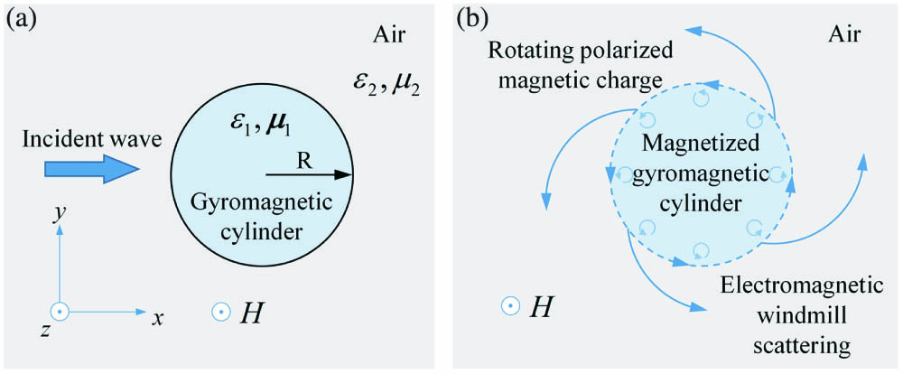
    Fig. 1. Model and physics. (a) Geometry model of analytical theory. (b) Physical mechanism of electromagnetic windmill scattering.
    Numerical calculation results of R1 = 4.20 mm. (a) t = 0T, (b) t = T/4, (c) t = T/2, (d) t = 3T/4.
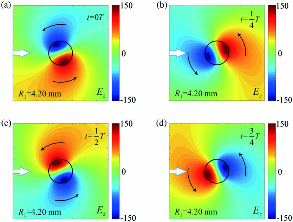
    Fig. 2. Numerical calculation results of R1 = 4.20 mm. (a) t = 0T, (b) t = T/4, (c) t = T/2, (d) t = 3T/4.
    Numerical calculation results of R2 = 6.76 mm. (a) t = 0T, (b) t = T/4, (c) t = T/2, (d) t = 3T/4.
    Fig. 3. Numerical calculation results of R2 = 6.76 mm. (a) t = 0T, (b) t = T/4, (c) t = T/2, (d) t = 3T/4.
    Energy flux (Poynting vector) distribution of unidirectional windmill scattering. (a) R1 = 4.20 mm, (b) R2 = 6.76 mm. The thick white arrows indicate the left-incident plane wave at f = 4.0 GHz. The thin white arrows represent the energy flux distribution, and the directions of the thin white arrows indicate the transport direction of energy fluxes.
    Fig. 4. Energy flux (Poynting vector) distribution of unidirectional windmill scattering. (a) R1 = 4.20 mm, (b) R2 = 6.76 mm. The thick white arrows indicate the left-incident plane wave at f = 4.0 GHz. The thin white arrows represent the energy flux distribution, and the directions of the thin white arrows indicate the transport direction of energy fluxes.
    Polarized magnetic charge distribution of a magnetized gyromagnetic cylinder with R1 = 4.20 mm.
    Fig. 5. Polarized magnetic charge distribution of a magnetized gyromagnetic cylinder with R1 = 4.20 mm.
    Polarized magnetic charge distribution of a magnetized gyromagnetic cylinder with R2 = 6.76 mm.
    Fig. 6. Polarized magnetic charge distribution of a magnetized gyromagnetic cylinder with R2 = 6.76 mm.
    Numerical calculation results of the incident plane waves in different directions. (a), (b) Magnetized gyromagnetic cylinder. (c), (d) Nonmagnetized gyromagnetic cylinder. (a), (c) Right-incident. (b), (d) Up-incident.
    Fig. 7. Numerical calculation results of the incident plane waves in different directions. (a), (b) Magnetized gyromagnetic cylinder. (c), (d) Nonmagnetized gyromagnetic cylinder. (a), (c) Right-incident. (b), (d) Up-incident.
    Normalized scattering spectra varying with the radius of the magnetized gyromagnetic cylinder. Three insets indicate the electric field and energy flux distributions of R1, R2, and R3.
    Fig. 8. Normalized scattering spectra varying with the radius of the magnetized gyromagnetic cylinder. Three insets indicate the electric field and energy flux distributions of R1, R2, and R3.
    Jianfeng Chen, Jianbo Pan, Yidong Zheng, Wenyao Liang, Zhi-Yuan Li. Unidirectional electromagnetic windmill scattering in a magnetized gyromagnetic cylinder[J]. Chinese Optics Letters, 2022, 20(5): 053901
    Download Citation