• Chinese Journal of Lasers
  • Vol. 49, Issue 2, 0202020 (2022)
Xiaohui Han1, Zhiyi Zhang1, Guolong Ma1, Laijun Wu2、3, Xiaoguo Song2、3, Houqin Wang2, and Caiwang Tan2、3、*
Author Affiliations
  • 1CRRC Qingdao Sifang Co., LTD., Qingdao, Shandong 266111, China
  • 2State Key Laboratory of Advanced Welding and Joining, Harbin Institute of Technology, Harbin, Heilongjiang 150001, China
  • 3Shandong Provincial Key Laboratory of Special Welding Technology, Harbin Institute of Technology at Weihai, Weihai, Shandong 264209, China
  • show less
    DOI: 10.3788/CJL202249.0202020 Cite this Article Set citation alerts
    Xiaohui Han, Zhiyi Zhang, Guolong Ma, Laijun Wu, Xiaoguo Song, Houqin Wang, Caiwang Tan. Effects of Heat Source Angle on Weld Formation and Porosity Defects of Laser-MIG Hybrid Welding of 6A01 Aluminum Alloy[J]. Chinese Journal of Lasers, 2022, 49(2): 0202020 Copy Citation Text show less
    Aluminum extrusions. (a) Appearances; (b) welds
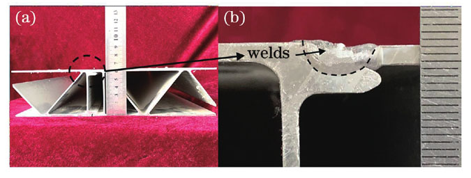
    Fig. 1. Aluminum extrusions. (a) Appearances; (b) welds
    Laser-MIG hybrid welding processing
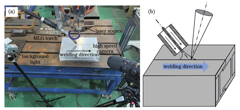
    Fig. 2. Laser-MIG hybrid welding processing
    Angle settings of the heat source in six tests. (a) Test 1; (b) test 2; (c) test 3; (d) test 4; (e) test 5; (f) test 6
    Fig. 3. Angle settings of the heat source in six tests. (a) Test 1; (b) test 2; (c) test 3; (d) test 4; (e) test 5; (f) test 6
    Weld appearances and cross-sections under different angle settings. (a) Test 1, α=82.5°,β=120°;(b) test 2, α=82.5°,β=140°;(c) test 3, α=70°,β=140°;(d) test 4, α=97.5°,β=120°;(e) test 5, α=97.5°,β=140°; (f) test 6, α=110°,β=140°
    Fig. 4. Weld appearances and cross-sections under different angle settings. (a) Test 1, α=82.5°,β=120°;(b) test 2, α=82.5°,β=140°;(c) test 3, α=70°,β=140°;(d) test 4, α=97.5°,β=120°;(e) test 5, α=97.5°,β=140°; (f) test 6, α=110°,β=140°
    Weld depth and width under different angle settings
    Fig. 5. Weld depth and width under different angle settings
    Steps for calculating weld porosity. (a) Cross-sections; (b) gray level image; (c) threshold segmentation
    Fig. 6. Steps for calculating weld porosity. (a) Cross-sections; (b) gray level image; (c) threshold segmentation
    Cross-sections and binary images of welds under different angle settings. (a) Test 1, α=82.5°,β=120°;(b) test 2, α=82.5°,β=140°;(c) test 3, α=70°,β=140°;(d) test 4, α=97.5°,β=120°;(e) test 5, α=97.5°,β= 140°;(f) test 6, α=110°,β=140°
    Fig. 7. Cross-sections and binary images of welds under different angle settings. (a) Test 1, α=82.5°,β=120°;(b) test 2, α=82.5°,β=140°;(c) test 3, α=70°,β=140°;(d) test 4, α=97.5°,β=120°;(e) test 5, α=97.5°,β=  140°;(f) test 6, α=110°,β=140°
    Porosity of welds under different angle settings
    Fig. 8. Porosity of welds under different angle settings
    Electricity signals, metal transfer and weld pool of welds under different angle settings. (a) Test 1, α=82.5°,β=120°;(b) test 2, α=82.5°,β=140°;(c) test 2, α=70°,β=140°;(d) test 4, α=97.5°,β=120°;(e) test 5, α= 97.5°,β=140°;(f) test 6, α=110°,β=140°
    Fig. 9. Electricity signals, metal transfer and weld pool of welds under different angle settings. (a) Test 1, α=82.5°,β=120°;(b) test 2, α=82.5°,β=140°;(c) test 2, α=70°,β=140°;(d) test 4, α=97.5°,β=120°;(e) test 5, α=  97.5°,β=140°;(f) test 6, α=110°,β=140°
    Fluent finite element simulation analysis modeling process. (a) Welding model; (b) meshing; (c) droplet settings
    Fig. 10. Fluent finite element simulation analysis modeling process. (a) Welding model; (b) meshing; (c) droplet settings
    Simulation results of the cross-sections and weld pool of welds under different angle settings. (a) Test 1, α=82.5°,β=120°;(b) test 2, α=82.5°,β=140°;(c) test 3, α=70°,β=140°;(d) test 4, α=97.5°,β=120°; (e) test 5, α=97.5°,β=140°;(f) test 6, α=110°,β=140°
    Fig. 11. Simulation results of the cross-sections and weld pool of welds under different angle settings. (a) Test 1, α=82.5°,β=120°;(b) test 2, α=82.5°,β=140°;(c) test 3, α=70°,β=140°;(d) test 4, α=97.5°,β=120°; (e) test 5, α=97.5°,β=140°;(f) test 6, α=110°,β=140°
    Comparison of simulation results and measured results of the weld depth and width. (a) Weld width; (b) weld depth
    Fig. 12. Comparison of simulation results and measured results of the weld depth and width. (a) Weld width; (b) weld depth
    MaterialsSiMnMgZnFeCrTiAl
    6A010.600.400.680.100.250.200.08Balance
    ER53560.250.205.500.100.400.200.20Balance
    Table 1. Chemical composition of used materials (mass fraction, %)
    Welding parametersValue
    Laser power /kW4
    Welding speed /(m·min-1)1.8
    Welding current /A180
    Welding voltage /V23
    Wire feeding speed /(m·min-1)8.1
    Distance between laser and arc /mm2
    Protect gas flow rate /(L·min-1)20
    Table 2. Processing parameters of laser-MIG hybrid welding
    Xiaohui Han, Zhiyi Zhang, Guolong Ma, Laijun Wu, Xiaoguo Song, Houqin Wang, Caiwang Tan. Effects of Heat Source Angle on Weld Formation and Porosity Defects of Laser-MIG Hybrid Welding of 6A01 Aluminum Alloy[J]. Chinese Journal of Lasers, 2022, 49(2): 0202020
    Download Citation