Yuan Yao, Haosen Shi, Guang Yang, Bo Li, Congyu Wang, Hongfu Yu, Longsheng Ma, Yanyi Jiang, "Coherent link between a Ti:sapphire comb and a 1.5 μm laser via nonlinear interaction in photonic crystal fiber," Photonics Res. 12, 350 (2024)
Copy Citation Text
【AIGC One Sentence Reading】:This study presents a novel approach to bridge the frequency gap between a 1550 nm laser and a Ti:sapphire comb using nonlinear interaction in a photonic crystal fiber, enabling precision optical frequency conversion for clock networks.
【AIGC Short Abstract】:This study presents a novel approach for bridging the frequency gap between optical clocks and the telecom band. By utilizing nonlinear interaction in a photonic crystal fiber, we link a 1550 nm laser and a Ti:sapphire-based optical frequency comb, enabling precision frequency conversion. The method demonstrates high signal-to-noise ratios and low additional noise, paving the way for enhanced time/frequency dissemination and fundamental research in optical clock networks.
Note: This section is automatically generated by AI . The website and platform operators shall not be liable for any commercial or legal consequences arising from your use of AI generated content on this website. Please be aware of this.
Abstract
Optical clock networks have distinct advantages for the dissemination of time/frequency, geodesy, and fundamental research. To realize such a network, the telecom band and optical atomic clocks have to be coherently bridged. Since the telecom band and optical atomic clocks reside in a distinct spectral region, second-harmonic generation is usually introduced to bridge the large frequency gap. In this paper, we introduce a new method to coherently link a 1550 nm continuous wave laser with a Ti:sapphire mode-locked laser-based optical frequency comb. By coupling the 1550 nm continuous wave laser light and the Ti:sapphire comb light together into a photonic crystal fiber, nonlinear interaction takes place, and new comblike frequency components related to the 1550 nm laser frequency are generated in the visible region. Consequently, we can detect beat notes between two combs in the visible region with a signal-to-noise ratio of more than 40 dB in a resolution bandwidth of 300 kHz. With this signal, we realize an optical frequency divider for converting the frequency of optical clocks in the visible region to the telecom band at 1.55 μm. An out-of-loop measurement shows that the additional noise and uncertainty induced in optical frequency conversion are at 1 s averaging time and , respectively, which are limited by the uncompensated light path fluctuation but fulfill precision measurement using state-of-the-art optical clocks.
1. INTRODUCTION
The frequency instability and uncertainty of the state-of-the-art optical atomic clocks approach [1,2]. Besides the next generation of SI second [3,4], optical atomic clocks are also powerful tools with unprecedented precision for exploration of our world, including measurement of the gravitational potential [1,5], tests of relativity [6–8], and search for dark matter [9,10]. Most of these precision measurements rely on frequency comparison between optical atomic clocks located in distant places. Networks of optical atomic clocks based on optical fibers [9–12] are constructed to realize the above applications as well as time and frequency dissemination on various occasions. However, the transmission bandwidth of optical communication network is restricted in the region ranged from 1.26 to 1.63 μm, while most optical clocks reside below 1.13 μm. Therefore, nonlinear optics, such as second-harmonic generation (SHG), are usually employed to connect optical atomic clocks with the telecom band.
Apart from frequency comparison between remote optical atomic clocks and frequency dissemination through optical fiber networks, there is growing interest in transferring the spectral purity of cryogenic silicon cavity-stabilized lasers at 1.5 μm to the clock transitions of optical clocks. By reducing the temperature of silicon cavities from room temperature down to 124 or 4 K, the cavity thermal noise-limited laser frequency instability can be eliminated from to [13,14]. By transferring the spectral purity of cryogenic silicon cavity-stabilized lasers at 1.5 μm to the local oscillators of optical atomic clocks, the frequency instability of optical clocks reaches unprecedented levels of at 1 s averaging time and at an averaging time of only 4000 s [15], benefitting from a reduced Dick effect.
Optical frequency combs (OFCs) provide a solution to link optical waves at different frequencies or to link optical waves and microwaves [16,17]. Erbium (Er)-doped fiber laser-based OFCs are used to transfer the frequency stability of a reference laser to a target laser in the infrared (IR) region, demonstrating that excess frequency instability in optical frequency transfer can be as low as at 1 s averaging time [18–20]. To link the frequencies between two lasers in the near IR and visible regions, Ti:sapphire mode-locked laser (Ti:Sa MLL)-based OFCs are employed. The lowest excess noise of at 1 s averaging time is demonstrated in optical frequency transfer [21].
Sign up for Photonics Research TOC. Get the latest issue of Photonics Research delivered right to you!Sign up now
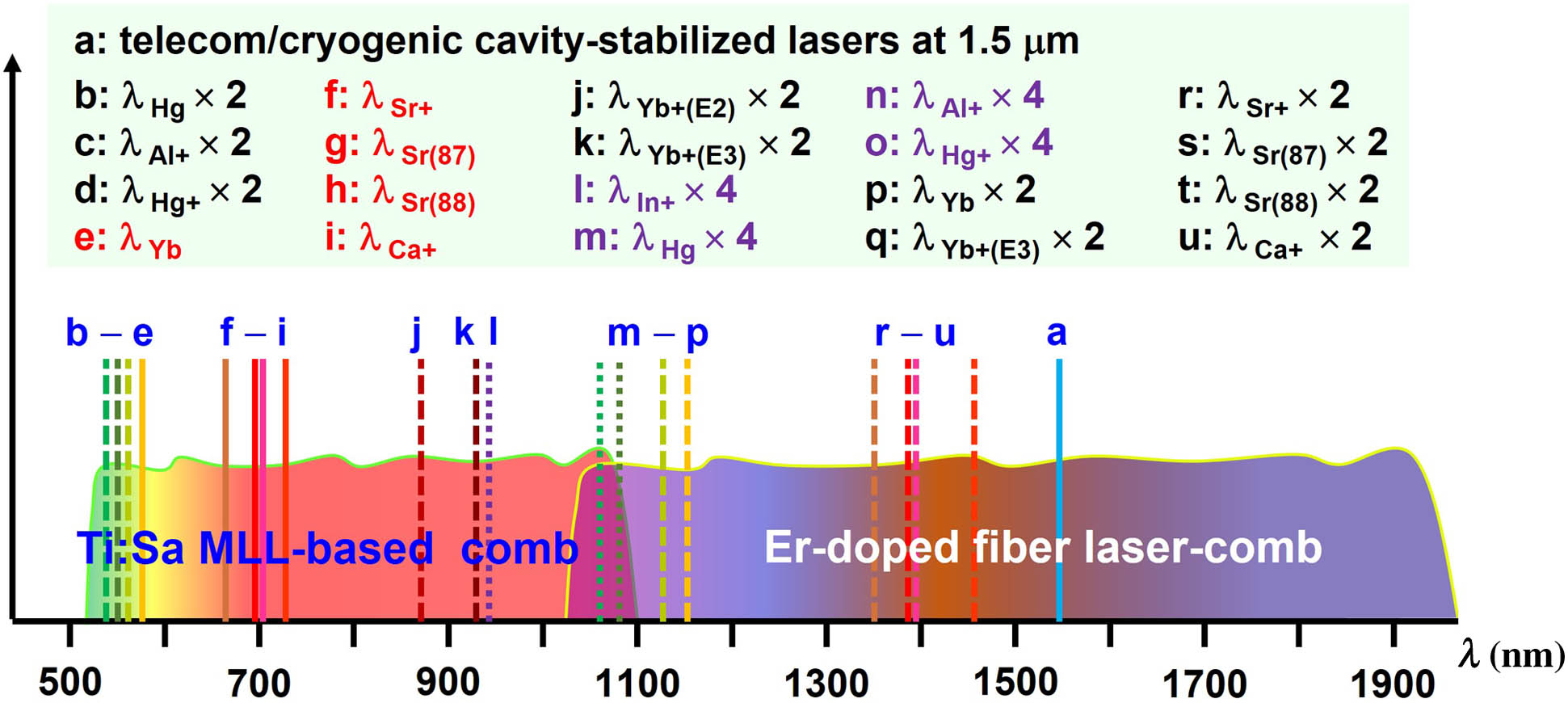
However, it is challenging to broaden the spectrum of an OFC in a single step to simultaneously cover the IR and visible regions, as shown in Fig. 1. In the case of Er-doped fiber laser-based OFC, its spectrum after broadening in a piece of nonlinear optical fiber usually covers 1–2 μm [19,20], in which dedicated optical amplifiers and nonlinear optical fibers are used to generate enough power for spectral broadening. Multibranch configuration is usually preferred for independent optimization of the beating signals with continuous wave (c.w.) lasers at interested spectral regions [22–26]. The differential phase noise induced by independent amplifiers, and an uncompensated effective light path between different branches limit the frequency instability in coherence transfer near or above at 1 s averaging time [22,23]. By actively compensating or electrically removing the interbranch differential phase noise, the excess frequency instability during optical frequency transfer can be reduced to at 1 s averaging time [23–26]. SHG is often employed to double the frequencies of Er-doped fiber laser-based OFC to reach the visible region. In some cases, Er-doped fiber laser-based combs directly beat against the fundamental light of optical atomic clocks, where SHG is employed to double the laser frequencies to the atomic transitions, as shown in Fig. 1. In the case of Ti:Sa MLL-based OFC, on the contrary, their spectra after broadening cover 0.5–1.1 μm, in which most optical clocks reside. However, they connect to the telecom band at 1.5 μm by doubling the frequencies of 1.5 μm lasers to the visible region via SHG. For Yb-doped fiber laser-based OFC (not shown in Fig. 1), their spectra after broadening cover 0.7–1.3 μm [27,28]. For all these OFCs, extra SHG is employed to reach the target spectral region.
Figure 1.Typical spectra of Ti:Sa MLL-based combs, Er-doped fiber laser-based combs, optical atomic clocks, and 1.5 μm fiber telecom band. Solid lines indicate the fundamental wavelength of optical atomic clocks; the dashed (dotted) lines represent () the wavelength of optical atomic clocks.
In this paper, we coherently link a Ti:Sa MLL-based OFC with a 1550 nm laser via nonlinear interaction in a piece of photonic crystal fiber (PCF). In 2013, a 1064 nm c.w. laser and the laser light from a Ti:Sa MLL at were coupled into a piece of PCF [29]. Consequently, a set of frequency modes with frequency spacings equal to the repetition rate () of the Ti:Sa MLL was generated via nonlinear process, and the beating signals between the newly generated frequency modes and the Ti:Sa comb can be detected at several distinct wavelengths within 532–1064 nm. Although the signal-to-noise ratio (SNR) of the beating signal detected at 532 nm was only 10 dB in a 300 kHz resolution bandwidth (RBW) at that time, it showed the possibility to link an OFC and a c.w. laser even if their spectra were not overlapped. In this paper, we coherently link a 1550 nm c.w. laser light and a Ti:Sa MLL-based OFC in a similar way. By coupling the 1550 nm laser light together with the light from the Ti:Sa MLL into a piece of PCF, the spectrum of the Ti:Sa MLL light is broadened to an octave; at the same time, new comblike frequency modes originating from the nonlinear interaction between the OFC and 1550 nm laser are generated in a broad spectral range. In such a simple experimental setup without SHG of the 1550 nm laser, we detect the beat note between two combs at several wavelengths in the visible region with a signal-to-noise ratio (SNR) of larger than 30 dB in an RBW of 300 kHz.
Besides this beat note, we also detect the beating signal between a 578 nm laser light and the Ti:Sa MLL-based comb and the comb carrier-envelope offset frequency (). With these signals, we realize an optical frequency divider (OFD) [21] to link the frequency of the 578 nm laser light, which works as the clock laser of an ytterbium optical clock, to the 1550 nm laser. The excess frequency instability induced in optical frequency division is measured to be at 1 s averaging time and at 1000 s averaging time by comparing against a second 1550 nm laser, which is referenced to the same 578 nm laser light via an independent optical frequency division. Such an out-of-loop measurement also shows that the uncertainty in optical frequency division is . Although the measured frequency instability and uncertainty in optical frequency division are limited by the uncompensated light path fluctuation, this measurement shows that it can support the networks of the state-of-the-art optical clock as well as coherence transfer from cryogenic silicon cavity-stabilized lasers at 1.5 μm to the clock transitions of optical clocks.
2. COHERENTLY LINK A 1550 nm LASER TO A Ti:Sa COMB
The experimental schematic is shown in Fig. 2(a). Part of the Ti:Sa MLL light (Novanta, Taccor 10) with a repetition rate of combines with the 1550 nm c.w. laser light before the PCF rather than after the PCF in conventional methods. Then, the combined laser light is coupled into a piece of PCF (NKT, FemtoWhite 800), whose zero-dispersion wavelength is at and 1260 nm. Therefore, the output wavelength of the Ti:Sa MLL at is in the anomalous dispersion region. The nonlinear coefficient of the PCF at 780 nm is . At the output of the PCF, the light power from the Ti:Sa MLL (1550 nm c.w. laser) is 260 (0.8) mW.
Figure 2.(a) Experimental schematic for the detection of the beat note between the Ti:Sa MLL-based comb and a 1550 nm c.w. laser. It also shows the optical spectrum of the Ti:Sa MLL-based comb (solid lines) and the newly generated comb based on FWM (brown dashed lines). (b) Beat note of separately detected at 1550 nm (green), 780 nm (red), and 590 nm (blue) in an RBW of 300 kHz. The abscissas of the spectra are intentionally shifted to be clearly seen. (c) SNR of in an RBW of 300 kHz detected at different wavelengths when the polarization of the PCF input light is fixed.
The high nonlinearity and dispersion design of the PCF facilitate the supercontinuum generation of the Ti:Sa MLL light. The frequency of the spectrally broadened Ti:Sa MLL light can be expressed as where is an integer related to the th comb mode. To simplify, we use the plus sign before in the following text. Meanwhile, nonlinear processes take place in the presence of the 1550 nm c.w. laser. Cross-phase modulation (XPM) leads to frequency sidebands close to the 1550 nm c.w. laser, whose frequency is expressed as with an integer. Four-wave mixing (FWM) is also obtained with the Ti:Sa MLL light as the pump and 1550 nm c.w. laser as the optical seed when phase-matching condition is satisfied. The frequency of anti-Stokes light is expressed as where and are the frequencies of the pump light (the Ti:Sa MLL-based OFC here) and the 1550 nm c.w. laser light, and and are the mode number of the Ti:Sa MLL-based OFC. In Eq. (2), we focus on the anti-Stokes light since we detect the beat note at a wavelength in the visible region. As shown in Eq. (2), a set of new frequency components with a frequency spacing of is generated. We denote it a newly generated frequency comb arising mainly from the nonlinear effect of FWM. Moreover, the sidebands with a frequency of at originating from cross-phase modulation can also be the optical seed of FWM. In this case, the frequency of this newly generated comb originated from cascade nonlinear effects is expressed the same as Eq. (2). The dashed lines in the inset of Fig. 2(a) represent the newly generated OFC mainly based on FWM; the solid lines represent the spectrally broadened Ti:Sa MLL-based OFC.
We detect the beat note between the two combs in the visible region where the spectra of the two combs overlap. A grating and a slit are employed to select the spectral band for detection. The frequency of the beat note is expressed as where is the mode number of the detected Ti:Sa comb light. Since is below 1 GHz, the first term on the right side of Eq. (3) is close to . As shown in Eq. (3), the beat note of links the frequencies of the 1550 nm c.w. laser light and the Ti:Sa MLL-based comb.
Although the newly generated FWM comb cannot be obviously observed on an optical spectrum analyzer owing to its relatively low power, the beat note between the two combs with a high SNR can be detected since a number of comb teeth mutually contribute to the beat signal, and the spatial modes of the two combs are perfectly matched.
We detect the beat note of at and , as shown in Fig. 2(b). The SNR of detected at 590 nm can be (), which is high enough for phase-locking. The signal of detected at 1550 nm is the beating signal between the spectrally broadened Ti:Sa comb (which may be enhanced near 1550 nm in the presence of the 1550 nm c.w. laser) and the cross-phase modulated frequency sidebands beside the 1550 nm c.w. laser, similar to that in Ref. [29]. We explore the SNR of detected at a wavelength in the region of 570 to 620 nm, as shown in Fig. 2(c). In this measurement, we did not change the polarization of the input light. When we change the polarization of the PCF input light, we can also optimize the SNR of detected at a certain wavelength, i.e., 575 nm, which can be slightly higher than that shown in Fig. 2(c).
Here, we use the PCF to generate the FWM-based comb. In principle, devices such as waveguides [30–34] can also be used to generate supercontinuum and nonlinear interaction-assisted frequency combs. When using devices with customized dispersion design instead of the commercial PCF as used here, the detection efficiency of the beat note between two combs will be even higher. Compared with the conventional method, in which SHG is employed to double the frequency of a 1550 nm laser to the visible region and then beat against a Ti:Sa MLL light, the method described here has three advantages. First, there is no need of second-harmonic crystals and related temperature stabilization to double the laser frequency at telecom band or double the frequency of optical atomic clocks. Second, the detection bandwidth can be tens of nanometers, as shown in Fig. 2(c); while using the conventional method, it is usually about 1 nm to meet the phase matching in the second-harmonic crystal. Third, the total light power of the 1550 nm laser is about 10 mW, which is much less than that needed for second-harmonic generation. In conclusion, using the method described in this paper, the experimental setup is simpler and is more efficient.
3. FREQUENCY DIVIDING FROM OPTICAL CLOCKS TO TELECOM
A. Experimental Setup
In order to transfer the coherence and frequency accuracy between the 1550 nm c.w. laser and another c.w. laser in the visible region, i.e., a cavity-stabilized laser at 578 nm as the local oscillator of an ytterbium optical clock in this paper, we need to obtain the signals of (i) , (ii) , and (iii) the beat note between the 578 nm laser and the OFC. The signal of is detected using a collinear 1f–2f self-referencing interferometer [35]. In order to optimize the SNR of and independently, the output laser light of the Ti:Sa MLL is split into two beams, as shown in Fig. 3(a), and each beam is separately coupled into a piece of PCF. By beating the 578 nm c.w. laser light against the Ti:Sa comb light output from the same PCF that generates , the beat note of is detected, which can be expressed as where is the frequency of the 578 nm c.w. laser, and is the th comb mode near .
Figure 3.(a) Experimental diagram for optical frequency division from a cavity-stabilized laser at 578 to 1550 nm and its out-of-loop measurement. (b) Electrical diagram to obtain the error signal of Δ for phase-locking the 1550 nm c.w. laser to the cavity-stabilized laser at 578 nm. The frequency noise from the comb is subtracted with the transfer oscillator scheme. (c) Simplified diagram for testing the noise in coherence transfer from the cavity-stabilized laser at 578 nm to the 1550 nm c.w. laser. We use a multichannel optical frequency division based on a single comb to characterize an out-of-loop measurement. We use different methods to obtain the beat notes between the 1550 nm lasers and the comb. (d) Fractional frequency instability of the phase-locked (in-loop, black squares) and the beat note () between the two 1550 nm c.w. lasers (out-of-loop, blue dots).
In order to keep the beating signals within the passband of the radio frequency (RF) filters and to extend the continuous-operation time of the Ti:Sa MLL-based OFC as well, we stabilize the comb ( and ) to the signals synthesized from a hydrogen maser, whose frequency instability is at 1 s averaging time. To subtract the comb frequency noise in the coherence transfer or optical frequency division, we employ the transfer oscillator scheme [36] based on RF double balanced mixers and direct digital synthesizers (DDSs). As shown in Fig. 3(b), as a result, we obtain a signal free of and as where and are the divisors of DDS and are set to satisfy . We phase-lock to a signal of synthesized from an optically referenced RF time base of at 10 MHz, where is a divisor independent on any external RF reference [21,37]. By adjusting the frequency of the 1550 nm c.w. laser, the 1550 nm c.w. laser is phase-locked to the cavity-stabilized laser at 578 nm as where the divisor satisfies , and is a divisor of a DDS, which is used to generate from . The divisor can be precisely preset by setting the divisors of the DDS, as shown in Fig. 3(b).
B. Performance Evaluation
To demonstrate the in-loop noise, the frequency of is mixed down to ; it is then filtered by a 1.9 MHz low-pass filter and recorded on a frequency counter (K + K FXE). The counter is in a “frequency average” mode with a gate time of 1 s and the time base of . As shown with the black squares in Fig. 3(d), the fractional frequency instability of is at 1 s averaging time and at 1000 s averaging time. The in-loop frequency instability represents the ultimate limit of the frequency transfer.
To make an out-of-loop measurement, we introduce a second 1550 nm c.w. laser with a frequency denoted as , whose laser light is sent to the platform where the Ti:Sa MLL is via a piece of polarization maintenance (PM) fiber. A simplified diagram for the out-of-loop measurement is shown in Fig. 3(c). To fully characterize the detection method of via the FWM-based comb, in the out-of-loop measurement we use a conventional method to detect the beat note between the OFC and the 1550 nm test laser. The 1550 nm test laser light is frequency-doubled in a periodically poled lithium niobate (PPLN) crystal. The c.w. laser light at 1550 and 775 nm is output from the PPLN with a power of 70 and 1 mW, respectively. Then, the laser light is combined with the comb light output from the PCF, as shown in Fig. 3(a). The beat note between the second harmonic at 775 nm and the Ti:Sa MLL-based comb is detected. The signal of together with the signals of and is employed to realize optical frequency division from the 578 nm laser to the 775 nm test laser and thereby to the fundamental light at 1550 nm. Thus, where is the divisor of the second channel of the OFD.
The beat note between and is detected after the PCF in Fig. 3(a). By recording the frequency of , the potential difference between two optical frequency divisions will be observed. The frequency instability of in terms of Allan deviation is at 1 s averaging time and averages down to at 1000 s, as shown by the blue dots in Fig. 3(d). The fractional frequency instability is limited by the fluctuation of uncommon light path between two 1550 nm lasers with a length of . We have independently measured the frequency instability induced by the fluctuation of the uncommon light path, which shows a similar instability to that shown in Fig. 3(d). Although the out-of-loop frequency instability at 1000 s is 10 times larger than the in-loop measurement, it is still lower than the frequency instability of the state-of-the-art optical atomic clocks by nearly an order of magnitude.
We calculate the value of based on the measured and known . The whole data set taken on three different days is divided into nearly 70 groups of subdata sets with 1000 s continuous measurement time, and we obtain the mean value of for each sub-dataset. Using standard statistical methods, the measured value of is found to deviate from its set value by , which is nearly five times smaller than the most accurate optical atomic clocks [1,2]. Such an optical frequency divider connecting optical atomic clocks and the telecom is suitable in the networks of the state-of-the-art optical atomic clocks. It will be applicable in the development of optical atomic clocks with high-frequency stability and the applications of optical atomic clocks in precision measurement for its simplified experimental setup with fewer optical amplifiers and second-harmonic crystals.
4. CONCLUSION
In summary, we develop and characterize a new method to link the telecom band at 1.5 μm with a Ti:Sa MLL-based OFC. The frequency instability induced during the coherence transfer is measured to be at 1 s averaging time, and it averages down to at 1000 s. The frequency uncertainty in optical frequency division is . This method is applicable to transfer the frequency and coherence between optical atomic clocks and the telecom band, which is critical in optical clock networks for tests of fundamental physics and precision spectroscopy with cryogenic cavity stabilized ultrastable lasers. In principle, the method can also be applicable to other OFCs, including fiber laser-based OFCs.
Acknowledgment
Acknowledgment. We thank A. Bartels for prompt technical support on the turnkey Ti:sapphire mode-locked laser.
Yuan Yao, Haosen Shi, Guang Yang, Bo Li, Congyu Wang, Hongfu Yu, Longsheng Ma, Yanyi Jiang, "Coherent link between a Ti:sapphire comb and a 1.5 μm laser via nonlinear interaction in photonic crystal fiber," Photonics Res. 12, 350 (2024)
 AI Video Guide
  AI Picture Guide
 AI One Sentence