• Laser & Optoelectronics Progress
  • Vol. 58, Issue 21, 2108001 (2021)
Xueliang Kang1、*, Chengxiang Shi1, Li Wang1、2, Qilong Liu1, Rui Xue1, Tingting Ren1, Weikang Sun1, and Xiantao Wei3
Author Affiliations
  • 1School of Electrical & Information Engineering, North Minzu University, Yinchuan , Ningxia 750021, China
  • 2School of Mechanical Engineering, Hefei University of Technology, Hefei , Anhui 230009, China
  • 3School of Physical Sciences, University of Science and Technology of China, Hefei , Anhui 230026, China
  • show less
    DOI: 10.3788/LOP202158.2108001 Cite this Article Set citation alerts
    Xueliang Kang, Chengxiang Shi, Li Wang, Qilong Liu, Rui Xue, Tingting Ren, Weikang Sun, Xiantao Wei. Characteristics of Collimating Illumination System with Extended Source Based on Total-Internal-Reflection Lens[J]. Laser & Optoelectronics Progress, 2021, 58(21): 2108001 Copy Citation Text show less
    TIR collimating lens. (a) Diagram of section structure; (b) stereograms of different perspectives
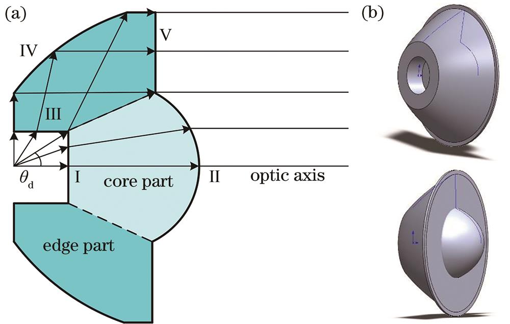
    Fig. 1. TIR collimating lens. (a) Diagram of section structure; (b) stereograms of different perspectives
    Schematic diagram of surface shape and light collimation of TIR collimating lens with 100-nm aperture
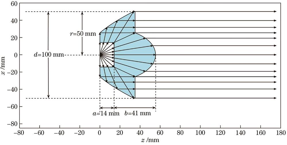
    Fig. 2. Schematic diagram of surface shape and light collimation of TIR collimating lens with 100-nm aperture
    One-dimension intensity I distribution of outgoing beams from each part and entirety of TIR collimating lens. (a) Core part; (b) edge part; (c) entirety
    Fig. 3. One-dimension intensity I distribution of outgoing beams from each part and entirety of TIR collimating lens. (a) Core part; (b) edge part; (c) entirety
    Two-dimension illuminance E distribution of entire outgoing beams from TIR collimating lens at different illumination distances. (a) 55 mm away from source; (b) 150 mm away from source; (c) 260 mm away from source; (d) 360 mm away from source; (e) 490 mm away from source; (f) 860 mm away from source; (g) 1.2 m away from source; (h) 1.4 m away from source; (i) 12 m away from source
    Fig. 4. Two-dimension illuminance E distribution of entire outgoing beams from TIR collimating lens at different illumination distances. (a) 55 mm away from source; (b) 150 mm away from source; (c) 260 mm away from source; (d) 360 mm away from source; (e) 490 mm away from source; (f) 860 mm away from source; (g) 1.2 m away from source; (h) 1.4 m away from source; (i) 12 m away from source
    One-dimension illuminance E distribution of the outgoing beams from each part and entirety of TIR collimating lens at different illumination distances. (a) 55 mm away from source; (b) 150 mm away from source; (c) 260 mm away from source; (d) 360 mm away from source; (e) 490 mm away from source; (f) 860 mm away from source; (g) 1.2 m away from source; (h) 1.4 m away from source; (i) 12 m away from source
    Fig. 5. One-dimension illuminance E distribution of the outgoing beams from each part and entirety of TIR collimating lens at different illumination distances. (a) 55 mm away from source; (b) 150 mm away from source; (c) 260 mm away from source; (d) 360 mm away from source; (e) 490 mm away from source; (f) 860 mm away from source; (g) 1.2 m away from source; (h) 1.4 m away from source; (i) 12 m away from source
    One-dimension intensity I distribution of outgoing beams from each part and entirety of TIR collimating lens with 150 mm aperture. (a) Core part; (b) edge part; (c) entirety
    Fig. 6. One-dimension intensity I distribution of outgoing beams from each part and entirety of TIR collimating lens with 150 mm aperture. (a) Core part; (b) edge part; (c) entirety
    Two-dimension illuminance E distribution of entire outgoing beams from TIR collimating lens at different illumination distances. (a) 1.1 m away from source; (b) 2.65 m away from source; (c) 18 m away from source
    Fig. 7. Two-dimension illuminance E distribution of entire outgoing beams from TIR collimating lens at different illumination distances. (a) 1.1 m away from source; (b) 2.65 m away from source; (c) 18 m away from source
    One-dimension illuminance E distribution of outgoing beams from each part and entirety of TIR collimating lens at different illumination distances. (a) 1.1 m away from source; (b) 2.65 m away from source; (c) 18 m away from source
    Fig. 8. One-dimension illuminance E distribution of outgoing beams from each part and entirety of TIR collimating lens at different illumination distances. (a) 1.1 m away from source; (b) 2.65 m away from source; (c) 18 m away from source
    Schematic diagram of surface shape and light collimation of plano-convex lens with 30° collecting angle
    Fig. 9. Schematic diagram of surface shape and light collimation of plano-convex lens with 30° collecting angle
    One-dimension intensity I distribution of outgoing beams from plano-convex collimating lens
    Fig. 10. One-dimension intensity I distribution of outgoing beams from plano-convex collimating lens
    Two-dimension (left) and one-dimension (right) illuminance E distribution of plano-convex collimating lens at different illumination distances. (a) 116 mm away from source; (b) 10 m away from source
    Fig. 11. Two-dimension (left) and one-dimension (right) illuminance E distribution of plano-convex collimating lens at different illumination distances. (a) 116 mm away from source; (b) 10 m away from source
    Comparison of light distribution effects of various light distribution elements. (a) Intensity distribution; (b) one-dimension illuminance distribution at 25 m away from source
    Fig. 12. Comparison of light distribution effects of various light distribution elements. (a) Intensity distribution; (b) one-dimension illuminance distribution at 25 m away from source
    Photos of various light distribution elements.(a)TIR lens with 100-mm aperture;(b)TIR lens with 150-mm aperture;(c)plano-convex lens
    Fig. 13. Photos of various light distribution elements.(a)TIR lens with 100-mm aperture;(b)TIR lens with 150-mm aperture;(c)plano-convex lens
    Illumination spots of various collimating illumination systems. (a) TIR lens with 100-mm aperture; (b) TIR lens with 150-mm aperture; (c) plano-convex lens
    Fig. 14. Illumination spots of various collimating illumination systems. (a) TIR lens with 100-mm aperture; (b) TIR lens with 150-mm aperture; (c) plano-convex lens
    Measured one-dimension illuminance E distribution of various collimating illumination systems
    Fig. 15. Measured one-dimension illuminance E distribution of various collimating illumination systems
    Type of light distribution elementAperture 2r /mmIntensity I /cdDivergence angle /(°)Flux utilization η /%
    θ1/2θ1/10
    TIR1009.8×1042.84.588.4
    TIR1502.2×1051.83.189.0
    Plano-convex1008.8×1041.61.820.8
    Table 1. Comparison of light distribution characteristics of various light distribution elements

    Type of light

    distribution element

    Aperture

    2r /mm

    IlluminationE /lxSpot radiusR /mDivergence angle /(°)Flux utilizationη /%
    TIR100150.41.33.081.4
    TIR150328.80.92.185.1
    Plano-convex100136.50.71.617.2
    Table 2. Comparison of measured performance parameters of various collimating illumination systems
    Xueliang Kang, Chengxiang Shi, Li Wang, Qilong Liu, Rui Xue, Tingting Ren, Weikang Sun, Xiantao Wei. Characteristics of Collimating Illumination System with Extended Source Based on Total-Internal-Reflection Lens[J]. Laser & Optoelectronics Progress, 2021, 58(21): 2108001
    Download Citation