• Photonics Research
  • Vol. 10, Issue 4, 1097 (2022)
Hui-Jun Zhao1, Fei Fan1、2、*, Tian-Rui Zhang1, Yun-Yun Ji1, and Sheng-Jiang Chang1、2
Author Affiliations
  • 1Institute of Modern Optics, Nankai University, Tianjin Key Laboratory of Micro-scale Optical Information Science and Technology, Tianjin 300350, China
  • 2Tianjin Key Laboratory of Optoelectronic Sensor and Sensing Network Technology, Tianjin 300350, China
  • show less
    DOI: 10.1364/PRJ.453082 Cite this Article Set citation alerts
    Hui-Jun Zhao, Fei Fan, Tian-Rui Zhang, Yun-Yun Ji, Sheng-Jiang Chang. Dynamic terahertz anisotropy and chirality enhancement in liquid-crystal anisotropic dielectric metasurfaces[J]. Photonics Research, 2022, 10(4): 1097 Copy Citation Text show less

    Abstract

    To enhance and actively control terahertz (THz) anisotropy and chirality, we have designed and fabricated a THz composite device with a liquid crystal (LC) layer and Si anisotropic metasurface. By initial anchoring and electrically rotating the spatial orientation of the LC optical axis, the different symmetry relationships are obtained in this hybrid device. When the optical axis of LC is parallel or perpendicular to the optical axis of the Si metasurface, the anisotropy of the device will be enhanced or offset, which leads to a tunable phase-shift range of more than 180°. When there is an angle between the two optical axes, due to the destruction of the mirror symmetry in the LC-Si anisotropic medium, the highest circular dichroism of the device reaches 30 dB in the middle orientation state of the LC optical axis, and the active modulation can be realized by changing the bias electric field on the LC layer. This composite device demonstrates rich characteristics for the feasible manipulation of THz polarization conversion and chiral transmission, which can be applied in THz polarization imaging and chiral spectroscopy.

    1. INTRODUCTION

    Terahertz (THz) technology defined within the electromagnetic frequency band of 10111013  Hz has broad application prospects due to its unique electromagnetic characteristics and spectral position [13]. The flexible manipulations of THz phase, polarization, and chirality provide key support for THz application systems in multichannel communication, beam tracking and radar detection, polarization imaging, and chiral biochemical detection, and so on [46]. However, the limited natural anisotropic crystal materials in the THz band limit the development of THz phase and polarization control elements. Moreover, since the wavelength of THz waves is much longer than that of general chiral molecular structures, there are few reports on natural materials with chiral responses in the THz band [7,8]. Fortunately, with the development of artificial microstructure devices (such as metasurface, subwavelength grating, and photonic crystal) in recent years, the electromagnetic anisotropy and artificial chiral response have been realized by introducing the geometric symmetry breaking of artificial structures. The structures with a spatial orientation or rotational symmetry breaking will bring artificial anisotropy to show birefringence phase shift and polarization conversion [911], while the structures with significant mirror symmetry breaking will show optical chirality [1215], that is, a pair of the conjugated circularly polarized (CP) state has different transmittance (i.e., circular dichroism, CD) or phase shift (i.e., optical activity, OA) in this structure.

    These artificial phase shift, polarization, and chiral THz devices are expected to further obtain the ability of dynamic control. However, the anisotropic phase shift or the chiral response of these devices comes from the asymmetric geometry of the devices. Once the device structure has been fabricated, it is often difficult to change except by mechanical deformation [16,17]. A common strategy is to introduce functional materials, such as graphene and vanadium oxide (VO2) into these microstructures, which respond significantly to light, electric field, and magnetic field, to realize the dynamic devices [1820]. For example, Kim et al. achieved an active graphene chiral metamaterial with 45 dB intensity modulation in THz CD [21]. Nakata et al. used the VO2 phase transition to equivalently change the metasurface structure and realize the active inversion of the output THz chiral state [22]. However, graphene or VO2 itself does not have anisotropy, so the anisotropy or chirality excitation can only rely on artificial structures, while these functional materials mainly play the role of active intensity modulation, to achieve the switching function of the polarization conversion and chirality state. Therefore, the strong response, bandwidth, larger tuning range, and more flexible control methods for THz anisotropy and chirality manipulation still face challenges [2325].

    Unlike graphene, semiconductors, and phase change materials, liquid crystals (LCs) have remarkable uniaxial anisotropy in the THz regime, which can be flexibly manipulated by thermal, optical, electric, or magnetic fields [2628]. The strategy of combining LCs with metasurfaces has been widely applied in active THz phase, polarization, and wavefront elements [20,2931]. For example, Chen et al. demonstrated THz modulation and polarization conversion using bidirectional switching of LCs in the ultrabroadband THz range of 0.2–1.6 THz [32]. Buchnev et al. reported that a THz spatial phase modulator was demonstrated at 0.8 THz with the thickness of the LC layer of only 12 μm (0.03λ) and a spatial resolution of 85 μm (0.23λ) [33]. Liu et al. and Wu et al. reported the programmable LC metasurface for THz beam steering [34,35]. However, the role of LC in these works is refractive index change or birefringence phase shift, and the LC itself has no THz chiral response. Although Zhang et al. showed strong THz OA and CD in the cholesteric LC, it occurred at the low temperature of 250 K [36]. In the visible near-infrared band, Liu et al. obtained tunable optical chirality response and photonic spin state by combining the anisotropic LCs with a chiral metasurface [37,38]. However, the physical mechanism and relevant LC devices have not been deeply studied to further enhance tunable anisotropy and chirality in the THz band.

    In this work, we have studied the combination and relationship between natural anisotropy of LC materials and artificial anisotropy of a microstructure to solve the above issue. A tunable THz LC-Si anisotropic metasurface has been investigated by using the THz time-domain polarization spectroscopy (THz-TDPS) system, as shown in Fig. 1. By initial anchoring and electrically rotating the spatial orientation of the LC optical axis, the different symmetry relationships in this device lead to an enhanced anisotropic phase shift and adjustable intrinsic chirality. Compared with the pure LC layer without metasurface, the maximum phase shift of the device increases from 160° to 360° at 1 THz. More importantly, combining two kinds of achiral material and structure, i.e., nematic LCs and Si metasurface, obtains up to 30 dB THz CD by applying the appropriate initial anchoring and bias electric field on the LC layer.

    (a) SEM photo of Si dielectric metasurface. (b) Schematic diagram of terahertz TDPS system. (c) Structural diagram of LC-Si metasurface. d) Experimental configuration of LC-Si metasurface.

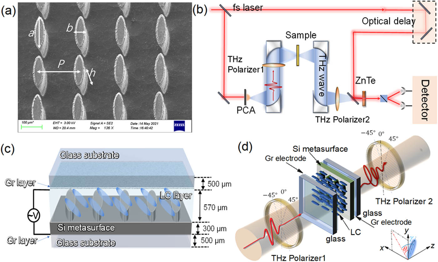
    Figure 1.(a) SEM photo of Si dielectric metasurface. (b) Schematic diagram of terahertz TDPS system. (c) Structural diagram of LC-Si metasurface. d) Experimental configuration of LC-Si metasurface.

    2. METHOD

    A. Device Fabrication

    The structure of the LC-Si metasurface is shown in Figs. 1(c) and 1(d), which consists of two fused-silica substrates as an LC cell and two graphene conductive layers coated on their inner surfaces as THz LC transparent electrodes. An all-dielectric metasurface fabricated on a high-resistance Si substrate and a high-birefringence LC layer are both encapsulated in this LC cell. As shown in Fig. 1(c), the device structure from top to bottom is as follows: the top glass substrate, the top graphene electrode layer, LC layer, Si metasurface, the bottom graphene electrode layer, and the bottom glass substrate. The Si metasurface was fabricated on a high-resistance Si substrate of >10  ·cm and 500 μm thickness by the processing of the photolithography and reactive ion-beam etching. As shown in Fig. 1(a), the dielectric metasurface is squarely arrayed as the elliptical Si columns with a period of P=200  μm, column height h=200  μm, long axis of the ellipse a=142  μm, and short axis b=38  μm. The remaining Si substrate has a thickness of 300 μm. Such a structure has asymmetry in spatial orientation, so this Si metasurface has artificial anisotropy for THz waves.

    Two pieces of 500 μm thick fused-silica glass were used to make the LC cells. The graphene-dispersed solution was spin-coated on the glass surface with a rotating speed of 500 r/min and a running time of 1 min. Then, it was dried at 80°C to obtain a porous graphene conductive layer with a thickness of 500 nm. As shown in Fig. 1(c), the Si metasurface and two glass sheets with top and bottom graphene electrodes and their conductors were curled into a cell with ultraviolet glue; finally, this LC cell was encapsulated after injecting the LC material. The LCs are located between the top graphene electrode and the Si metasurface; note that the gap between the Si columns is also filled with LCs. The total thickness of the LC layer, including the 200 μm thickness of the Si columns, is 570 μm. The LC material used in this work is a kind of high-birefringence nematic LC (HTD028200) purchased from Jiangsu Hecheng Technology Co., Ltd. Its birefringence coefficient is Δn=0.3. The transition temperature from solid to nematic state is TSN=30°C; the transition temperature from nematic state to isotropic state (i.e., clearing point) is TSI=103°C; it also has good thermal stability in the nematic state. A pair of rotatable permanent magnets can be placed by the two sides of the LC cell to apply a biased magnetic field of 70 mT in the xy plane to replace the anchoring layer for the initial LC orientation. By applying a 1 kHz alternating electric field with the tunable bias to the upper and lower electrodes, we can control the LC turns from the xy plane to the z-axis direction.

    B. Experiment System

    We conduct our experiments by using the THz-TDPS system, as shown in Fig. 1(b). The THz pulse is generated by a GaAs photoconductive antenna, and a 110 ZnTe crystal is used for the electro-optic sampling THz detection. The excitation source is a Ti:sapphire laser of 800 nm with an 80 fs duration. All experiments were carried out at room temperature (20°C±5°C) and relative humidity <30%. The measured sample is placed in the focus point of the system. A pair of THz metallic wire polarizers is placed in front of and behind the sample. This THz polarizer is a metallic grating composed of freestanding metallic tungsten wires with a diameter of 10 μm and spacing of 25 μm. The polarizer has nearly 100% transmittance and more than 99.8% polarization degree in the THz frequency range discussed in this work. To detect the arbitrary polarization state of the emitted light, we can obtain the transmission amplitude A+45°, A45° and the phase φ+45°,φ45° for the ±45° linearly polarized (LP) components by rotating the second THz polarizer to ±45° [36,39]. Hence, for each incident LP state, the transmissions of the output left circularly polarized (LCP) and right circularly polarized (RCP) components are given by (ERCPELCP)=12(1i1i)(E+45°E45°)=12(1i1i)(A+45°eiδ+45°A45°eiδ45°).

    To intuitively describe the arbitrary polarization state of the output light, we can calculate the terminal trajectory equation of electric vector E, that is, polarization ellipse, as follows: (ExA+45°)2+(EyA45°)22ExEyA+45°A45°cosΔφ=sin2Δφ,where the phase difference Δφ=φ+45°φ+45°. Two polarization parameters, i.e., the polarization ellipticity angle (PEA) and the polarization rotation angle (PRA), can be obtained by PEA=arcsin(sin2εsinΔφ)/2,PRA=arctan(tan2εcosΔφ)/2,where tanε=A+45°/A45°.

    To further obtain the whole polarization and chiral response of the device, it is necessary to input a pair of orthogonal polarization states. For the CP base vector, the outputs are two converted (trl and tlr) and two unconverted (trr and tll) states. The first subscript indicates the polarization state of the output component; the latter represents the polarization state of the input wave. To obtain these four CP states, we can measure the four linear co- and cross-polarization transmission coefficients t++45°, t+45°, t+45°, and t45° by rotating both THz polarizers to ±45° in the THz-TDPS system, respectively. The transmission matrix T of a chiral device can be calculated as follows [40,41]: T=(trrtrltlrtll)=12((t++45°+t45°)+i(t+45°t+45°)(t++45°t45°)i(t+45°+t+45°)(t++45°t45°)+i(t+45°+t+45°)(t++45°+t45°)i(t+45°t+45°)).

    C. Si Metasurface without LC and LC without Metasurface

    We have experimentally measured the anisotropic transmission and birefringence phase shift of this Si metasurface without LC, as shown in Figs. 2(a) and 2(b). The intensity spectra along the long and short axes are different. There are two resonances at 0.9 and 1.4 THz along the long axis, respectively, while there is a resonance at 1.25 THz along the short axis. The phase delay in the long axis direction is higher than that in the short axis direction, forming the birefringence effect, as shown in Fig. 2(b). The structure has an anisotropic phase shift of 66° at 0.75 THz; a phase shift mutation caused by artificial resonance occurs in the frequency band of 0.9–1 THz; thus, the phase shift reaches 240° at 1.15 THz, but this phase shift cannot be actively tuned.

    Experimental results of Si metasurface without filling LC. (a) LP transmission spectra when the polarization direction of the incident LP wave is along the long axis and short axis of the Si columns. (b) Birefringence phase shifts in these two orthogonal directions. (c) Transmission spectra through the blank fused-silica LC cell, the complete blank LC cell with two graphene electrode layers, and the LC cell with LC but without Si metasurface as LC orientation along x, y, and z axes; inset figure: SEM photo of graphene electrode layer. (d) Birefringence phase shift in two orthogonal directions of this LC cell under different biased electric fields.

    Figure 2.Experimental results of Si metasurface without filling LC. (a) LP transmission spectra when the polarization direction of the incident LP wave is along the long axis and short axis of the Si columns. (b) Birefringence phase shifts in these two orthogonal directions. (c) Transmission spectra through the blank fused-silica LC cell, the complete blank LC cell with two graphene electrode layers, and the LC cell with LC but without Si metasurface as LC orientation along x, y, and z axes; inset figure: SEM photo of graphene electrode layer. (d) Birefringence phase shift in two orthogonal directions of this LC cell under different biased electric fields.

    The transmittance of the empty LC cell is higher than 3 dB in the THz band of 0.2–1.3 THz, and the transmittance decreases slightly after coating the graphene layer, as shown in Fig. 2(c). The graphene layer is formed to be a porous film on the surface after drying the graphene-dispersed liquid, of which an SEM photo is shown in Fig. 2(c). The conductivity has been measured to be 1000 S/m. Due to the porous structure, it maintains high transmittance to THz waves under a high conductivity. When the LC cell is filled with a 570 μm LC layer, the spectra of LC along the x, y-, and z directions are also as shown in Fig. 2(c), all of which have high transmittance.

    When the molecules in the LC layer are arranged regularly, the LC will also have anisotropy, which is different from the fixed optical axis orientation of the Si column array. The optical axis orientation of the LC can rotate dynamically with the control of the external field. By applying a transverse magnetic field bias of 70 mT, the LC molecules can be initially arranged in the xy plane when there is no biased electric field, where we define the orientation angle θ between the long axis of the LC molecule orientation and the y axis. We applied a 1 kHz biased electric field on the graphene electrodes to drive the rotation of LC molecules. With the increase of bias electric field from 0 to 30 V/mm, the long axis of LC molecules will turn from the xy plane to the z axis, where we define another orientation angle γ between the long axis of the LC molecule orientation and the xy plane. Therefore, the spatial orientation of LC is described by θ and γ, which are determined by the pre-anchoring direction and the biased electric field, respectively. The following work discusses the device properties caused by different geometric symmetries of devices under different LC orientations (θ,γ). We have also measured the anisotropic phase shift of the LC layer without Si metasurface as shown in Fig. 2(d). When the LC turns to the z axis from 0 to 30 V/mm, the birefringence gradually disappears and the phase shift decreases to 0. This phase shift also increases linearly with the frequency of incident waves. The results show that the maximum phase shift of this LC cell is 120° at 0.75 THz and 160° at 1 THz.

    3. RESULTS AND DISCUSSION

    A. Engineering THz Anisotropy in LC-Si Metasurface

    Next, we discuss the results of the composite metadevice combined with the LC layer and Si column array. First, we discuss the simplest case: the LC initial anchoring direction is parallel or perpendicular to the long axis of the Si column, as illustrated in Fig. 3(a). Therefore, when E=0  V/mm (i.e., γ=0°) and θ=0°, the optical axis of LC is parallel to the long axis of the Si column, the LC birefringence is superimposed with the artificial birefringence of Si column, and the whole device obtains an enhanced anisotropic phase shift. On the contrary, when θ=90°, the optical axis of the LC is orthogonal to the long axis of the Si column, and the LC birefringence effect offsets the artificial birefringence of the Si column, the anisotropic phase shift of the device is weakened. When the bias electric field is applied, the LC begins to turn to the z axis (i.e., γ>0°). For the light propagating along the z axis, the effective anisotropy effect of LC decreases whether the initial anchoring angle θ=0° or 90°; finally, when γ=90°, the contribution of LC to anisotropy disappears, and the anisotropic phase shift will only be determined by the geometric anisotropy of the Si column, and the level is in the middle of the two cases above.

    (a) Geometric diagram of LC molecular orientation in LC-Si metasurface: when the biased electric field E=0 V/mm, the LC molecule is initially anchored in the y axis (θ=0°, γ=0°) and anchored in the x axis (θ=90°, γ=0°); when E=30 V/mm, the LC molecule is turned to the z axis (γ=90°); the long axis of the Si column is fixed along the y axis. The experimental THz time-domain signals for x−LP and y−LP components with a biased electric field applied from 0 to 30 V/mm when the LC is initially along (b) the y axis and (c) the x axis. (d) The experimental phase shift of the device under the different initial orientations and biased electric fields.

    Figure 3.(a) Geometric diagram of LC molecular orientation in LC-Si metasurface: when the biased electric field E=0  V/mm, the LC molecule is initially anchored in the y axis (θ=0°, γ=0°) and anchored in the x axis (θ=90°, γ=0°); when E=30  V/mm, the LC molecule is turned to the z axis (γ=90°); the long axis of the Si column is fixed along the y axis. The experimental THz time-domain signals for xLP and yLP components with a biased electric field applied from 0 to 30 V/mm when the LC is initially along (b) the y axis and (c) the x axis. (d) The experimental phase shift of the device under the different initial orientations and biased electric fields.

    We carried out the experimental verification. The long axis of the Si column in the LC-Si metasurface is fixed along the y axis, as shown in Fig. 3(a). When x- and y-LP waves are incident into this device, according to the geometric and dielectric symmetry of the device, the polarization states of these two LP waves will not change. As shown in Figs. 3(b) and 3(c), the time delay of the pulse indicates the value of the phase shift through the device. Note that only the phase in the direction of LC initial orientation decreases with the increase of the bias electric field, but the phase in the orthogonal polarization direction remains unchanged. The delay in the x and y directions in Fig. 3(b) increases with the decrease of the bias, while the pulse in the y direction in Fig. 3(c) always partially overlaps with the pulse in the y direction, although the pulse delay in the x direction also shifts with the changes of the bias. Therefore, for the case of θ=0° shown in Fig. 3(d), the phase difference between the x and y directions increases with the decrease of the bias field; however, for the case of θ=90°, the phase difference decreases with the reduction of the bias.

    The maximum anisotropic phase shift of the LC-Si metadevice is obtained when the optical axis of the LC is parallel to the optical axis of the Si metasurface. The detailed phase shift is 180° at 0.75 THz and 360° at 1 THz in this case, which is much higher than the phase shift values (120° at 0.75 THz and 160° at 1 THz) when there is only the LC layer with the same thickness. The range surrounded by hollow and solid red lines is the maximum tunable phase range of this metadevice by rotating the initial anchoring angle θ with the external magnetic field. This range is from 50°to180° at 0.75 THz and 60° to 360° at 1 THz, which can be achieved via a tunable half-wave plate. Therefore, the experimental results confirm that the enhanced tunable phase-shift range can be realized by introducing artificial anisotropy and reasonably matching between the optical axis of LC and the optical axis of the dielectric metasurface.

    B. Mirror Symmetry Breaking Mechanism in LC-Si Metasurface

    When there is an included angle (θ0° or 90°) between the optical axis of LC and the optical axis of Si metasurface, as shown in Fig. 4(a), this is equivalent to the existence of two spatially noncoincident optical axes in the transmission system, and the mirror symmetry of the transmission system along the propagation direction (z axis) is broken in this case. In this system, the transmission properties of LCP and RCP waves will be different; that is, they show intrinsic optical chiral response. Meanwhile, unlike uniaxial optical crystals, the incident LP waves with any polarization angle will change their polarization states. Figure 4(a) shows the (θ=45°, γ=0°) case, which just fits our analysis above. With the increase of bias electric field, the optical axis of LC begins to shift from the position of the xy plane (45° to the y axis) to the z axis (γ0°). Compared with the case of (θ=45°, γ=0°), the level of mirror symmetry breaking is more significant when θ=45° and γ=45°, as shown in Fig. 4(b). When the optical axis continues to rotate, this asymmetry decreases until it completely disappears along the z axis, as shown in Fig. 4(c). Therefore, the THz optical chirality of the device can be dynamically manipulated by actively changing the spatial angle between the LC orientation and the long axis of the anisotropic metasurface.

    Geometric diagram of LC molecular orientation in LC-Si metasurface when the LC is initially anchored θ=45° to the y axis and the angle (a) γ=0°, (b) 45°, and (c) 90° to the x−y plane, which corresponds to the biased field E=0, 15, and 30 V/mm cases, respectively. The long axis of the Si column is fixed along the y axis. (d) FDTD simulation of electric field distribution in the LC-Si metasurface when θ=45° and γ=0°, 45°, and 90° at 0.95 THz.

    Figure 4.Geometric diagram of LC molecular orientation in LC-Si metasurface when the LC is initially anchored θ=45° to the y axis and the angle (a) γ=0°, (b) 45°, and (c) 90° to the xy plane, which corresponds to the biased field E=0, 15, and 30 V/mm cases, respectively. The long axis of the Si column is fixed along the y axis. (d) FDTD simulation of electric field distribution in the LC-Si metasurface when θ=45° and γ=0°, 45°, and 90° at 0.95 THz.

    We have conducted the preliminary verification through the finite difference time domain (FDTD) simulation. Numerical simulations were modeled by using the commercial software Lumerical FDTD Solution. The periodic boundary conditions were applied at the x and y boundaries. The z boundaries were surrounded by perfectly matched layers. The refractive indices of Si and glass were set to 3.4 and 1.9, respectively. The LC layer was modeled as a uniaxial anisotropy material, and its extraordinary and ordinary refractive indices (ne and no) are set to 1.9 and 1.6, respectively. To represent the rotation of the LC optical axis in this work, the dielectric constant of LC needs to be expressed in a tensor form in the simulation. This anisotropic dielectric tensor can take any spatial orientation angle (θ,γ) through a certain orthogonal coordinate transformation from the original diagonal tensor. Figure 4(d) shows the three electric field patterns for LC orientation angles θ=45° and γ=0°, 45°, and 90° correspond to the cases shown in Figs. 4(a)–4(c), respectively. For γ=0°, the electric field inside the device shows weak asymmetry and rotation around the Si column; for γ=45°, the electric field rotates strongly clockwise around the Si column and has obvious optical chirality; for γ=90°, the electric field is completely symmetrical about the Si column and only resonates in the Si column without rotation, i.e., there is no optical chirality.

    C. Tunable Polarization and Chirality States in LC-Si Metasurface

    Next, we carry out the experimental verification of the above theoretical analysis. The original experimental data are the time-domain signals of ±45° orthogonal LP components input by a pair of ±45° orthogonal LP light. Under different bias electric fields, the four groups of component signals tested by the THz-TDPS system are shown in Fig. 5. (See Section 2.B for the experimental principle and data processing method.) As shown in Figs. 5(a) and 5(b), we detect a co-polarized component parallel to the original 45° LP component and an orthogonal cross-polarized component. With the decrease of bias electric field, the phase of the co-polarization component gradually increases, and the amplitude decreases; while the phase of the cross-polarization component also increases and the amplitude increases significantly. It shows that the polarization conversion effect of the whole device is weak along the z axis (γ=90°) but strong in the xy plane (θ=45°, γ=90°). Figures 5(c) and 5(d) show a similar result for the 45° LP incidence. However, the four groups of component signals are different under each bias electric field except for 30 V/mm, which indicates that the polarization response of the two groups of orthogonal LP light is quite different, suggesting the optical chirality of the device. The only exception is that, at 30 V/mm, the two cross-polarization signals are the same, indicating that, in this case, there is only polarization conversion but no chirality.

    Experimental THz time-domain signals from 1 to 7 ps delay for the four orthogonal polarization components of LC-Si metasurface, when initial LC orientation θ=45° with the biased electric field E=0–30 V/mm: (a) 45° LP incidence to 45° LP detection and (b) to −45° LP detection; (c) −45° LP incidence to −45° LP detection and (d) to 45° LP detection.

    Figure 5.Experimental THz time-domain signals from 1 to 7 ps delay for the four orthogonal polarization components of LC-Si metasurface, when initial LC orientation θ=45° with the biased electric field E=030  V/mm: (a) 45° LP incidence to 45° LP detection and (b) to 45° LP detection; (c) 45° LP incidence to 45° LP detection and (d) to 45° LP detection.

    We decompose the above outgoing wave into the conjugated LCP and RCP components according to Eq. (1) and analyze the amplitude and phase relationship between them, to obtain the polarization angle spectra and polarization states, as shown in Fig. 6. For the +45° LP incidence, the transmission spectra of LCP and RCP are shown in Fig. 6(a), which demonstrate that the two orthogonal CP components change continuously with the increase of bias electric field, and the two spectral lines are not the same under each bias; that is, the outgoing wave is no longer the original LP state but an elliptically polarized wave. Its polarization state is mainly described by the PEA and PRA, and their spectra are shown in Fig. 6(b). (See Section 2.B for the detailed definitions.) In the broadband range of 0.1–1.1 THz, when the bias electric field is high and the LC molecule tends to the z-axis arrangement, PEA and PRA are close to 0, and the polarization conversion is weak. When the bias decreases, however, both the PEA and PRA increase. For example, at 0.4 THz, as shown in Fig. 6(e), the ellipticity of the output polarization state gradually changes from approximate LP to ellipse with the decrease of the bias field; at 0.8 THz, the approximate LP is always output, but the polarization rotation angle changes from 0° to 45°. For the 45° LP incidence, as shown in Figs. 6(c), 6(d), and 6(f), the detailed spectral line and spin direction are different from that of the 45° case, but the regularity of active manipulation for the polarization conversion is the same.

    Experimental transmission spectra and polarization conversion when the initial LC orientation θ=45° and LP incidence with the biased electric field E=0–30 V/mm. For the 45° LP incidence: (a) transmission spectra of LCP and RCP output components; (b) PEA and PRA spectra; (e) polarization ellipse at 0.4 and 0.8 THz. For the −45° LP incidence: (c) transmission spectra of LCP and RCP output components; (d) PEA and PRA spectra; (f) polarization ellipse at 0.4 and 0.8 THz.

    Figure 6.Experimental transmission spectra and polarization conversion when the initial LC orientation θ=45° and LP incidence with the biased electric field E=030  V/mm. For the 45° LP incidence: (a) transmission spectra of LCP and RCP output components; (b) PEA and PRA spectra; (e) polarization ellipse at 0.4 and 0.8 THz. For the 45° LP incidence: (c) transmission spectra of LCP and RCP output components; (d) PEA and PRA spectra; (f) polarization ellipse at 0.4 and 0.8 THz.

    Further, from the symmetry analysis, it can be known that the polarization conversion effect occurs for arbitrary polarization states, and the output polarization states will not be the same under the same bias. This indicates that the response of the device to a single LP component cannot fully reflect the whole transmission and polarization characteristics of this LC-Si metadevice. Unless the incident waves are also a pair of orthogonal polarization signals, like completely detecting the four groups of orthogonal LP components signals in Fig. 5, the chiral characteristics of the device can be completely obtained. To better analyze the optical chiral response of the device, we transform them to the orthogonal CP basis as in Eq. (5). Figure 7 shows the transmission spectra of the four CP components: two co-polarization states (Tll and Trr) and the other two cross-polarization states (Trl and Tlr). It can be seen that, except for the case of 30 V/mm, they are different under the same bias field and are continuously tunable with the changes of the bias electric field. Corresponding to the experimental results, we simulated the response of the device to the LCP and RCP waves, respectively, and detect their unconverted and orthogonal converted components. In the simulation, the LC layer is set as an anisotropic tensor medium, and θ=45°, γ=0°90° to reflect the orientation of LC molecules with the changes of the bias field in the experiment. The simulation results in Figs. 7(b) and 7(d) show that the transmission spectra of the four CP components are in good agreement with that in the experiment shown in Figs. 7(a) and 7(c).

    CP transmission spectra for LCP and RCP incidence with the biased electric field E=0–30 V/mm when the initial LC orientation θ=45°: (a) experiment Tll and Trr; (b) simulation Tll and Trr; (c) experiment Trl and Trl; (d) simulation Trl and Trl.

    Figure 7.CP transmission spectra for LCP and RCP incidence with the biased electric field E=030  V/mm when the initial LC orientation θ=45°: (a) experiment Tll and Trr; (b) simulation Tll and Trr; (c) experiment Trl and Trl; (d) simulation Trl and Trl.

    To reflect the optical chirality response of the device, two chirality parameters, i.e., co-polarization circular dichroism (Co-CD) and cross-polarization circular dichroism (Cross-CD), can be obtained by Co-CD(dB)=10×log10TrrTllTrr+Tll,Cross-CD(dB)=10×log10TrlTlrTrl+Tlr,where Trr, Trl, Tlr, and Tll are the intensity transmission (in %). The Co-CD spectra in Figs. 8(a) and 8(b) are obtained according to the data in Fig. 7(a) and Eq. (6), which reflect the asymmetric transmission between two unconverted CP components. With the decrease of bias electric field from 30 to 15 V/mm, the Co-CD increases from 0 to a high value in the range of 0.8–1.5 THz and forms a negative peak at 0.95 THz and a positive one near 1.3 THz, respectively, reaching the maximum value of 30  dB at E=15  V/mm, as shown in Fig. 8(a). If we continue to reduce the bias electric field from 15 to 0 V/mm, as shown in Fig. 8(b), the Co-CD value turns to drop down from the maximum value to a small one. Therefore, the Co-CD experiences two modulation processes with the increase of the bias, first increasing and then decreasing, and the maximum modulation depth is 30 dB in the middle bias field.

    Experimental CD spectra of LC-Si metasurface with the different biased electric fields: (a) Co-CD with E=15–30 V/mm; (b) Co-CD with E=0–15 V/mm; (c) Cross-CD with E=0–30 V/mm. Simulative CD spectra of devices with the different LC orientation angle θ corresponding to the different electric fields E in the experiment when γ=45°: (d) Co-CD with γ=45°–90°; (e) Co-CD with γ=0°–45°; (f) Cross-CD with γ=0°–45°.

    Figure 8.Experimental CD spectra of LC-Si metasurface with the different biased electric fields: (a) Co-CD with E=1530  V/mm; (b) Co-CD with E=015  V/mm; (c) Cross-CD with E=030  V/mm. Simulative CD spectra of devices with the different LC orientation angle θ corresponding to the different electric fields E in the experiment when γ=45°: (d) Co-CD with γ=45°90°; (e) Co-CD with γ=0°45°; (f) Cross-CD with γ=0°45°.

    Figures 8(d) and 8(e) show the results of the corresponding numerical simulations, in which the LC optical axis orientation angle γ turns from 90° to 0°. When γ=90°, as shown in Fig. 8(d), that is, LC molecules are arranged strictly along the z axis, as shown in Fig. 4(c), the simulation results show that the chirality of this device is completely 0 in the broadband THz range. When γ=45°, the Co-CD value reaches the peak value; then, it decreases again as the γ decreases, but the Co-CD value is not equal to 0 when γ=0°. The spectral lines of numerical simulation are in good agreement with the experiment results, and the bias field applied in the experiment can correspond to the orientation angle in the simulation one by one. The experimental and simulation results confirm the analysis of mirror symmetry and chirality in Fig. 4. The results show that, when the orientation of LC molecules is in the middle state (θ=45°, γ=45°), the device can obtain the strongest THz optical chiral response.

    Figures 8(c) and 8(f) show the experimental and simulative Cross-CD spectra, respectively, which reflect the polarization conversion difference between LCP and RCP states. In the experiment, the dynamic process of Cross-CD is similar to that of Co-CD. When E=30  V/mm, there is only a cross-polarized CD of <10  dB near 1.3 THz in the whole band range. When E=15  V/mm, the strongest Co-CD of 30 dB is obtained at 1.25 THz. Then, it decreases slightly; however, when E=0  V/mm, there is still a strong Cross-CD of more than 15 dB. The simulated spectra are still in good agreement with the experimental ones. It also shows that, although the chirality in the LC initial anchoring state without electric bias (θ=45°, γ=0°) is weaker than that in the intermediate state (θ=45°, γ=45°), the cross chirality describing asymmetric polarization conversion is still significant, of which dynamic modulation depth also reaches 30 dB.

    In addition, the other parameter describing optical chirality is optical activity, which is the phase difference between LCP and RCP. The co-polarization optical activity (Co-OA) and co-polarization optical activity (Cross-OA) can be obtained by Co-OA(°)=φrrφll2,Cross-OA(°)=φrlφlr2,where φrr, φrl, φrl, and φll are the phase angle (in °). In fact, the CD spectrum and OA spectrum theoretically meet the Kramers–Kronig relationship [42], so if the CD spectrum changes, the OA spectrum will change accordingly. Figures 9(a) and 9(b) show the experimental Co-OA and Cross-OA spectra, respectively, and the OA angle can be actively tuned from 0° to 180°. In general, the experimental and numerical simulation results confirm the theoretical analysis in Fig. 4. The results indicate that the spatial orientation relationship and symmetry between the optical axis of LC and the optical axis of the dielectric metasurface can actively manipulate the anisotropy and chirality of the whole artificial metasurface device. The 30 dB strong intrinsic optical chirality of this metadevice is not from the molecular arrangement in LC material or the structure of dielectric metasurface but originates from the mirror-symmetry breaking of the equivalent dielectric tensor caused by the noncoincidence of the spatial orientation between the anisotropy of natural materials and artificial anisotropy of THz microstructure.

    Experimental OA spectra of LC-Si metasurface with the biased electric fields E=0–30 V/mm: (a) Co-OA; (b) Cross-OA.

    Figure 9.Experimental OA spectra of LC-Si metasurface with the biased electric fields E=030  V/mm: (a) Co-OA; (b) Cross-OA.

    4. CONCLUSION

    In summary, we have designed and fabricated a THz LC-Si anisotropic metasurface to actively control the THz anisotropy and chirality. By initial anchoring and electrically rotating the spatial orientation of the LC optical axis, the different symmetry relationships between the LC optical axis and the artificial anisotropic optical axis of the dielectric metasurface are obtained in this device. When the optical axis of LC is parallel or perpendicular to the optical axis of the Si metasurface, the anisotropy of the device will be enhanced or offset, which leads to the tunable phase-shift range of more than 180°. When there is an included angle between the two optical axes, the device exhibits THz chirality due to the mirror-symmetry breaking in this composite medium. The highest Co-CD and Cross-CD reach 30 dB in the middle orientation of LC (θ=45°, γ=45°), and the active modulation can be realized by changing the bias field. This composite device, based on the new mechanism of THz anisotropy engineering and chirality enhancement, demonstrates rich and dynamically adjustable polarization conversion and chiral asymmetric transmission characteristics, which can be applied in THz applications for polarization imaging, chiral spectroscopy, and multichannel communications.

    References

    [1] K. Sengupta, T. Nagatsuma, D. M. Mittleman. Terahertz integrated electronic and hybrid electronic–photonic systems. Nat. Electron., 1, 622-635(2018).

    [2] R. Y. Zhou, C. Wang, W. D. Xu, L. J. Xie. Biological applications of terahertz technology based on nanomaterials and nanostructures. Nanoscale, 11, 3445-3457(2019).

    [3] P. U. Jepsen, D. G. Cooke, M. Koch. Terahertz spectroscopy and imaging: modern techniques and applications. Laser Photon. Rev., 5, 124-166(2011).

    [4] T. Nagatsuma, G. Ducournau, C. C. Renaud. Advances in terahertz communications accelerated by photonics. Nat. Photonics, 10, 371-379(2016).

    [5] P. Doradla, K. Alavi, C. Joseph, R. Giles. Detection of colon cancer by continuous-wave terahertz polarization imaging technique. J. Biomed. Opt., 18, 090504(2013).

    [6] Z. Y. Zhang, C. Z. Zhong, F. Fan, G. H. Liu, S. J. Chang. Terahertz polarization and chirality sensing for amino acid solution based on chiral metasurface sensor. Sens. Actuators B Chem., 330, 129315(2021).

    [7] Y. Gao, S. Kaushik, E. J. Philip, Z. Li, Y. Qin, Y. P. Liu, W. L. Zhang, Y. L. Su, X. Chen, H. Weng, D. E. Kharzeev, M. K. Liu, J. Qi. Chiral terahertz wave emission from the Weyl semimetal TaAs. Nat. Commun., 11, 720(2020).

    [8] Z. Y. Tan, F. Fan, D. Zhao, Y. Y. Ji, J. R. Cheng, S. J. Chang. High-efficiency terahertz nonreciprocal one-way transmission and active asymmetric chiral manipulation based on magnetoplasmon/dielectric metasurface. Adv. Opt. Mater., 9, 2002216(2021).

    [9] J. C. Zi, Y. F. Li, X. Feng, Q. Xu, H. C. Liu, X. X. Zhang, J. G. Han, W. L. Zhang. Dual-functional terahertz waveplate based on all-dielectric metamaterial. Phys. Rev. Appl., 13, 034042(2020).

    [10] X. P. Dong, J. R. Cheng, F. Fan, S. T. Xu, X. H. Wang, S. J. Chang. Wideband sub-THz half-wave plate using 3D-printed low-index metagratings with superwavelength lattice. Opt. Express, 27, 202-211(2019).

    [11] X. G. Zhao, J. Schalch, J. D. Zhang, H. R. Seren, G. W. Duan, R. D. Averitt, X. Zhang. Electromechanically tunable metasurface transmission waveplate at terahertz frequencies. Optica, 5, 303-310(2018).

    [12] Y. Q. Tang, A. E. Cohen. Optical chirality and its interaction with matter. Phys. Rev. Lett., 104, 163901(2010).

    [13] M. Schaferling, D. Dregely, M. Hentschel, H. Giessen. Tailoring enhanced optical chirality: design principles for chiral plasmonic nanostructures. Phys. Rev. X, 2, 031010(2012).

    [14] X. H. Li, H. Zhao, C. Liu, J. Cai, Y. Zhang, Y. G. Jiang, D. Y. Zhang. High-efficiency alignment of 3D biotemplated helices via rotating magnetic field for terahertz chiral metamaterials. Adv. Opt. Mater., 7, 1900247(2019).

    [15] T. Lv, X. Chen, G. Dong, M. Liu, D. Liu, C. Ouyang, Z. Zhu, Y. Li, C. Guan, J. Han, W. Zhang, S. Zhang, J. Shi. Dual-band dichroic asymmetric transmission of linearly polarized waves in terahertz chiral metamaterial. Nanophotonics, 9, 3235-3242(2020).

    [16] T. Kan, A. Isozaki, N. Kanda, N. Nemoto, K. Konishi, H. Takahashi, M. Kuwata-Gonokami, K. Matsumoto, I. Shimoyama. Enantiomeric switching of chiral metamaterial for terahertz polarization modulation employing vertically deformable MEMS spirals. Nat. Commun., 6, 8422(2015).

    [17] L. Q. Cong, P. Pitchappa, N. Wang, R. Singh. Electrically programmable terahertz diatomic metamolecules for chiral optical control. Research, 2019, 7084251(2019).

    [18] S. Zhang, J. F. Zhou, Y. S. Park, J. Rho, R. Singh, S. Nam, A. K. Azad, H. T. Chen, X. B. Yin, A. J. Taylor, X. Zhang. Photoinduced handedness switching in terahertz chiral metamolecules. Nat. Commun., 3, 942(2012).

    [19] J. T. Li, J. Li, C. L. Zheng, S. L. Wang, M. Y. Li, H. L. Zhao, J. H. Li, Y. T. Zhang, J. Q. Yao. Dynamic control of reflective chiral terahertz metasurface with a new application developing in full grayscale near field imaging. Carbon, 172, 189-199(2021).

    [20] S. J. Kindness, N. W. Almond, W. Michailow, B. B. Wei, K. Delfanazari, P. Braeuninger-Weimer, S. Hofmann, H. E. Beere, D. A. Ritchie, R. Degl’Innocenti. A terahertz chiral metamaterial modulator. Adv. Opt. Mater., 8, 2000581(2020).

    [21] T. T. Kim, S. S. Oh, H. D. Kim, H. S. Park, O. Hess, B. Min, S. Zhang. Electrical access to critical coupling of circularly polarized waves in graphene chiral metamaterials. Sci. Adv., 3, e1701377(2017).

    [22] Y. Nakata, K. Fukawa, T. Nakanishi, Y. Urade, K. Okimura, F. Miyamaru. Reconfigurable terahertz quarter-wave plate for helicity switching based on babinet inversion of an anisotropic checkerboard metasurface. Phys. Rev. Appl., 11, 044008(2019).

    [23] X. Chen, H. Wang, H. Liu, C. Wang, G. Wei, C. Fang, H. Wang, C. Geng, S. Liu, P. Li, H. Yu, W. Zhao, J. Miao, Y. Li, L. Wang, T. Nie, J. Zhao, X. Wu. Generation and control of terahertz spin currents in topology-induced two-dimensional ferromagnetic Fe3GeTe2|Bi2Te3 heterostructures. Adv. Mater., 2106172(2021).

    [24] Y. Z. Hu, M. Y. Tong, X. A. Cheng, J. Zhang, H. Hao, J. You, X. Zheng, T. Jiang. Bi2Se3-functionalized metasurfaces for ultrafast all-optical switching and efficient modulation of terahertz waves. ACS Photon., 8, 771-780(2021).

    [25] Q. Y. Mu, F. Fan, S. Chen, S. T. Xu, C. Z. Xiong, X. Zhang, X. H. Wang, S. J. Chang. Tunable magneto-optical polarization device for terahertz waves based on InSb and its plasmonic structure. Photon. Res., 7, 325-331(2019).

    [26] L. Wang, S. J. Ge, W. Hu, M. Nakajima, Y. Q. Lu. Tunable reflective liquid crystal terahertz waveplates. Opt. Mater. Express, 7, 2023-2029(2017).

    [27] Y. Y. Ji, F. Fan, S. T. Xu, J. P. Yu, Y. Liu, X. H. Wang, S. J. Chang. Terahertz dielectric anisotropy enhancement in dual-frequency liquid crystal induced by carbon nanotubes. Carbon, 152, 865-872(2019).

    [28] C. F. Hsieh, C. S. Yang, F. C. Shih, R. P. Pan, C. L. Pan. Liquid-crystal-based magnetically tunable terahertz achromatic quarter-wave plate. Opt. Express, 27, 9933-9940(2019).

    [29] T. Sasaki, T. Asano, M. Sakamoto, K. Noda, T. Unuma, K. Goto, K. Tsutsui, N. Kawatsuki, H. Ono. Subwavelength liquid crystal gratings for polarization-independent phase shifts in the terahertz spectral range. Opt. Mater. Express, 10, 240-248(2020).

    [30] Y. Y. Ji, F. Fan, S. T. Xu, J. P. Yu, S. J. Chang. Manipulation enhancement of terahertz liquid crystal phase shifter magnetically induced by ferromagnetic nanoparticles. Nanoscale, 11, 4933-4941(2019).

    [31] Z. X. Shen, S. H. Zhou, X. A. Li, S. J. Ge, P. Chen, W. Hu, Y. Q. Lu. Liquid crystal integrated metalens with tunable chromatic aberration. Adv. Photon., 2, 036002(2020).

    [32] X. Q. Chen, K. D. Li, R. Zhang, S. K. Gupta, A. K. Srivastava, E. Pickwell-MacPherson. Highly efficient ultra-broadband terahertz modulation using bidirectional switching of liquid crystals. Adv. Opt. Mater., 7, 1901321(2019).

    [33] O. Buchnev, N. Podoliak, K. Kaltenecker, M. Walther, V. A. Fedotov. Metasurface-based optical liquid crystal cell as an ultrathin spatial phase modulator for THz applications. ACS Photon., 7, 3199-3206(2020).

    [34] C. X. Liu, F. Yang, X. J. Fu, J. W. Wu, L. Zhang, J. Yang, T. J. Cui. Programmable manipulations of terahertz beams by transmissive digital coding metasurfaces based on liquid crystals. Adv. Opt. Mater., 9, 2100932(2021).

    [35] J. B. Wu, Z. Shen, S. J. Ge, B. W. Chen, Z. X. Shen, T. F. Wang, C. H. Zhang, W. Hu, K. B. Fan, W. Padilla, Y. Q. Lu, B. B. Jin, J. Chen, P. H. Wu. Liquid crystal programmable metasurface for terahertz beam steering. Appl. Phys. Lett., 116, 131104(2020).

    [36] X. Zhang, F. Fan, Y. Y. Ji, S. J. Chang. Temperature-dependent chirality of cholesteric liquid crystal for terahertz waves. Opt. Lett., 45, 4988-4991(2020).

    [37] D. Xiao, Y. J. Liu, S. Yin, J. Liu, W. Ji, B. Wang, D. Luo, G. Li, X. W. Sun. Liquid-crystal-loaded chiral metasurfaces for reconfigurable multiband spin-selective light absorption. Opt. Express, 26, 25305-25314(2018).

    [38] S. Yin, D. Xiao, J. Liu, K. Li, H. He, S. Jiang, D. Luo, X. W. Sun, Y. J. Liu. Reconfigurable chiral metasurface absorbers based on liquid crystals. IEEE Photon. J., 10, 4600909(2018).

    [39] M. Shalaby, M. Peccianti, Y. Ozturk, M. Clerici, I. Al-Naib, L. Razzari, T. Ozaki, A. Mazhorova, M. Skorobogatiy, R. Morandotti. Terahertz Faraday rotation in a magnetic liquid: high magneto-optical figure of merit and broadband operation in a ferrofluid. Appl. Phys. Lett., 100, 241107(2012).

    [40] C. Menzel, C. Rockstuhl, F. Lederer. Advanced Jones calculus for the classification of periodic metamaterials. Phys. Rev. A, 82, 053811(2010).

    [41] Z. Wang, F. Cheng, T. Winsor, Y. Liu. Optical chiral metamaterials: a review of the fundamentals, fabrication methods and applications. Nanotechnology, 27, 412001(2016).

    [42] M. V. Gorkunov, V. E. Dmitrienko, A. A. Ezhov, V. V. Artemov, O. Y. Rogov. Implications of the causality principle for ultra chiral metamaterials. Sci. Rep., 5, 9273(2015).

    Hui-Jun Zhao, Fei Fan, Tian-Rui Zhang, Yun-Yun Ji, Sheng-Jiang Chang. Dynamic terahertz anisotropy and chirality enhancement in liquid-crystal anisotropic dielectric metasurfaces[J]. Photonics Research, 2022, 10(4): 1097
    Download Citation