
Qingsong Zhao, Shiqi Hao, Dai Zhang, Xiongfeng Wan. Effect of Single-Particle Scattering on Orbital Angular Momentum of Laguerre-Gaussian Beams[J]. Acta Optica Sinica, 2018, 38(6): 0629001
- Acta Optica Sinica
- Vol. 38, Issue 6, 0629001 (2018)
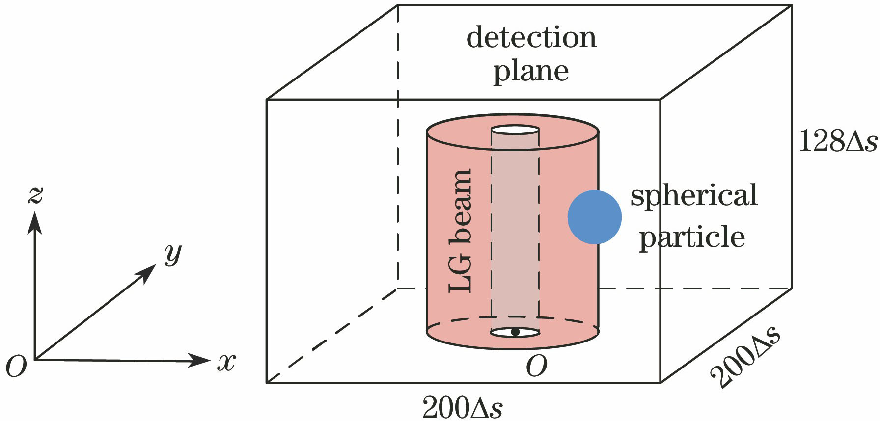
Fig. 1. Schematic of FDTD simulation domain
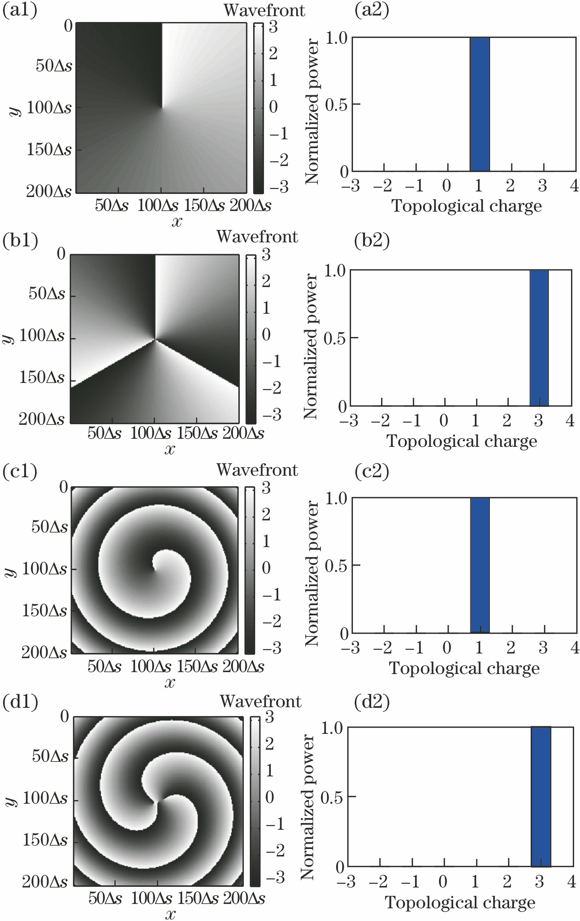
Fig. 2. (Left) wavefront distributions and (right) spiral spectra of LG beam. (a1)(a2) l=1, in waist plane; (b1)(b2) l=3, in waist plane; (c1)(c2) l=1, in detection plane; (d1)(d2) l=3, in detection plane
Fig. 3. (Left) wavefront distributions and (right) spiral spectra of LG beam in detection plane after scattering. (a1)(a2) l=1, particle center at (13Δs,0,64Δs), rd=20Δs; (b1)(b2) l=1, particle center at (13Δs,0,64Δs), rd=25Δs; (c1)(c2) l=3, particle center at (13Δs,0,64Δs), rd=20Δs; (d1)(d2) l=3, particle center at (25Δs,0,64Δs), rd=20Δs
Fig. 4. Pl of LG beam versus particle radius at different positions. (a) x=25Δs; (b) x=13Δs
Fig. 5. Schematic of relative positions between incident beam and scattering particles. (a) Particle moving along x-axis; (b) particle moving along z-axis
Fig. 6. Pl of LG beams with different topological charges versus particle off-axis distance. (a) l=1; (b) l=2; (c) l=3; (d) l=4
Fig. 7. Pl for of LG beams with different topological charges versus plane distance between particle and waist plane. (a) l=1; (b) l=2; (c) l=3; (d) l=4
Fig. 8. Schematic of scattering of ellipsoid particles. (a) Change of radii; (b) change of orientation
Fig. 9. Pl of LG beams with different topological charges versus ellipsoid-particle-radii ratio. (a) rb/ra; (b) rc/ra
Fig. 10. Pl of LG beams with different topological charges versus orientation angle of ellipsoidal particles

Set citation alerts for the article
Please enter your email address
© Copyright 2018-2021 | Chinese Laser Press. All Rights Reserved 沪ICP备15018463号-20