
Zezheng Li, Shuaipeng Guo, Chuang Jiang, Shaolin Ke, Zhennan Tian. Three-Dimensional Femtosecond-Laser Direct-Written Optical Waveguide: Advancements and Challenges (Invited)[J]. Chinese Journal of Lasers, 2024, 51(4): 0402406
- Chinese Journal of Lasers
- Vol. 51, Issue 4, 0402406 (2024)
![Three-dimensional optical waveguide devices fabricated by FsLDW technique[5-9]](/richHtml/zgjg/2024/51/4/0402406/img_01.jpg)
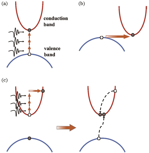
Fig. 2. Schematics of the free electron plasma formation. (a) Multiphoton ionization; (b) tunneling ionization; (c) avalanche ionization
Fig. 3. Schematics of the cross-section images of waveguides fabricated by FsLDW (the areas within the black dash lines represent the location of waveguide core). (a) Direct-written refractive index elevated waveguide; (b) stress-extruded dual line waveguide; (c) depressed cladding waveguide; (d) ablated ridge waveguide
Fig. 4. FIFO devices fabricated by FsLDW technique. (a) Sketch of the first FsLDW FIFO device for 4-core fiber[63]; (b) schematic of an FIFO device for 121-core fiber based on a photonic lantern[64]; (c) a fan-out device in optical quantum chips for the observation of N00N state Bloch oscillations[65]; (d) FsLDW prepared FIFO device with board-bandwidth and low insertion loss for 19-core fiber[66]
Fig. 5. Mode controlling devices fabricated by FsLDW technique. (a) Schematic of the first FsLDW OAM beam emitter[75]; (b) schematic of tapered couplers[76]; (c) concept and principle of the trench-based OAM mode multiplexer[5]
Fig. 6. 1×N splitters fabricated by FsLDW technique. (a) Schematic of the SLM-assisted single-sweep laser direct-written 1×4 splitter[83]; (b) schematic of three-dimensional LiNbO3 splitter based on depressed cladding waveguide[87]; (c)(d) schematic of splitter with the optical-lattice-like cladding and its output modal profile[88]
Fig. 7. Three-dimensional quantum photonic chips fabricated by FsLDW technique. (a) Schematic of the first three qubit quantum Toffoli gate[96]; (b) three-dimensional waveguide array for the two-mode braiding[6]; (c) the array with 2401 waveguides for two-dimensional quantum walks[98]; (d) three-waveguide coupled system introducing the birefringence[99]; (e) schematics for four-mode and eight-mode integrated interferometers for the implementation of qFFT[100]; (f) schematic of a glued hexagonal tree[101]
Fig. 8. Topological phase in optical waveguide arrays. (a) Spiral induced Floquet topological insulator[7]; (b) bulk band structure of Floquet topological insulators[7]; (c)(d) optical field distributions on the output surface of the waveguide array at different propagation distances[7]; (e) one-dimensional non-Hermitian SSH model[104]; (f) experimental and simulation results of mean displacement〈Δm〉for different distance differences Δd between waveguids[104]; (g) nonlinear induced photon anomalous Floquet topological insulator[105]; (h) bulk band structure of anomalous Floquet topological insulators[105]; (i) light diffraction in the anomalous Floquet arrays under linear and nonlinear edge excitation regimes[105]
Fig. 9. Three-dimensional optical waveguide devices for astrophotonics. (a) Schematic of the PL with Bragg gratings[110]; (b) schematic of the photonic dicer[8]; (c) schematic of the pupil remapper[111]; (d) schematic of three-dimensional beam combiner[112]
Fig. 10. Three-dimensional waveguide sensors. (a) Schematic of the femtosecond-laser-fabricated microfluidic channel and integrated MZI[117]; (b)(c) schematic of the RI sensor in silver containing glasses and transmission curves of the sensor under different refractive index oils[118]; (d) schematic of the cascaded FPI and MZI sensing structure[121]; (e) schematic of an HBGW created in coreless fiber[122]
Fig. 11. Spherical aberration and its compensation techniques. (a) Introduction of spherical aberration[138]; (b) schematic of the slit shaping optical path[145]; (c) optical microscopy photo of the circular cross-section optical waveguide written by the cylindrical lens and slit combination optical path and the scale bar is 10 μm[146]; (d) deep structures direct writing with the aid of SLM compensation algorithm[148]; (e) schematic of the multi-foci-shaped femtosecond laser direct writing optical path[150]
Fig. 12. Direct writing of large-depth waveguides by compensating the spherical aberration by SLM. (a) Symmetric cross-sections of waveguides written under different deptths[152]; (b) large-scale uniform waveguide array for achieving structural invisibility[153]
Fig. 13. Three-dimensional reconfigurable optical waveguides. (a) Depth-varying overpass waveguides[157]; (b) waveguide in a cantilever beam[158]
|
Table 1. Low-loss waveguides in various substrates fabricated by FsLDW technology

Set citation alerts for the article
Please enter your email address
© Copyright 2018-2021 | Chinese Laser Press. All Rights Reserved 沪ICP备15018463号-20