
Jun Wu, Xin Li, Shaoyu Liu, Yanling Li, Zhijing Yu. Global Three-Dimensional Reconstruction Method for Visual Detection of Aircraft Skin Damage Based on Rear Positioning[J]. Acta Optica Sinica, 2021, 41(11): 1115002
- Acta Optica Sinica
- Vol. 41, Issue 11, 1115002 (2021)
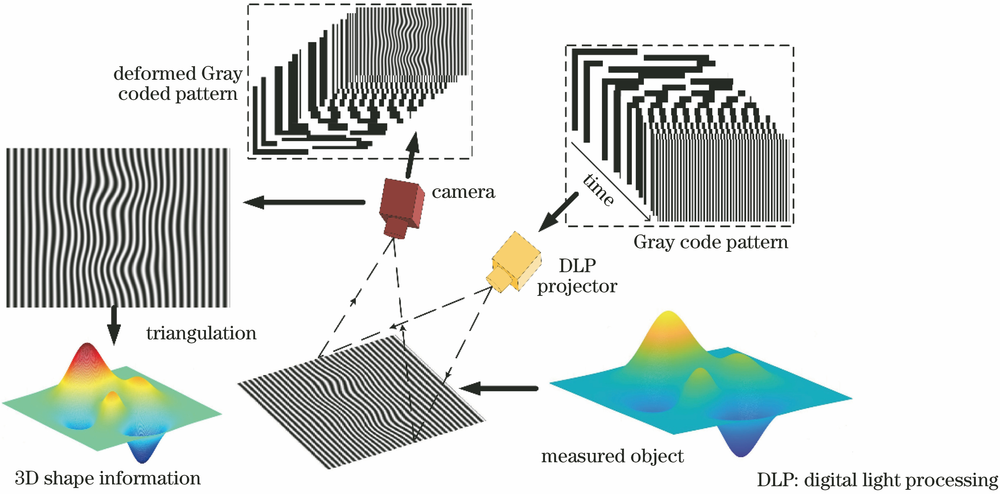
Fig. 1. Schematic diagram of 3D reconstruction of Gray code structured light
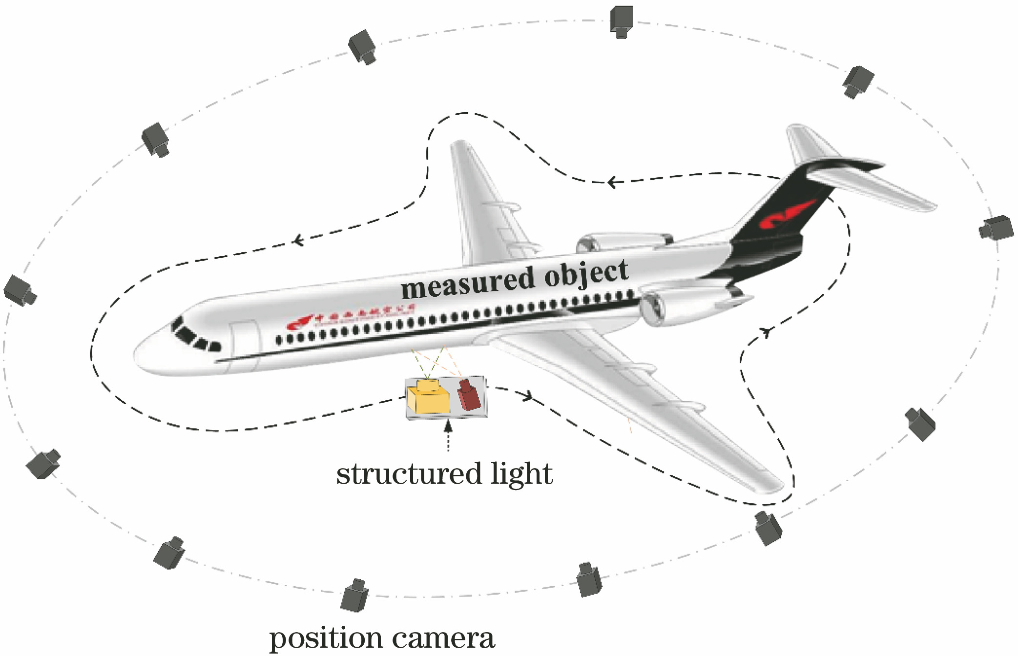
Fig. 2. Schematic diagram of global 3D reconstruction based on visual positioning of rear camera
Fig. 3. Improved structured light system diagram
Fig. 4. Schematic diagram of camera imaging model
Fig. 5. Self-calibration diagram of structured light system identification board
Fig. 6. Experimental flowchart of 3D reconstruction
Fig. 7. Calibration experimental diagram of structured light system
Fig. 8. Schematic diagram of 3D reconstruction experiment
Fig. 9. Point cloud data of aircraft global 3D reconstruction
Fig. 10. Reprojection error map
Fig. 11. Analysis of 3D reconstruction accuracy of structured light. (a) Step gauge block; (b) measured fringes; (c) average height of step gauge block
Fig. 12. Global 3D reconstruction accuracy analysis based on rear positioning. (a) Plate to be tested; (b) first position of measurement fringes; (c) point cloud error histogram
Fig. 13. ICP stitching results of point clouds. (a) Splicing result of point cloud at 1st and 2nd positions; (b) point cloud stitching results at 1st, 2nd, and 3rd positions
|
Table 1. Calibration results of structured light system

Set citation alerts for the article
Please enter your email address
© Copyright 2018-2021 | Chinese Laser Press. All Rights Reserved 沪ICP备15018463号-20