
Yaxin Zhang, Mingbo Pu, Yinghui Guo, Jinjin Jin, Xiong Li, Xiaoliang Ma, Xiangang Luo. Large field-of-view and compact full-Stokes polarimetry based on quadratic phase metasurface[J]. Infrared and Laser Engineering, 2020, 49(9): 20201030
- Infrared and Laser Engineering
- Vol. 49, Issue 9, 20201030 (2020)
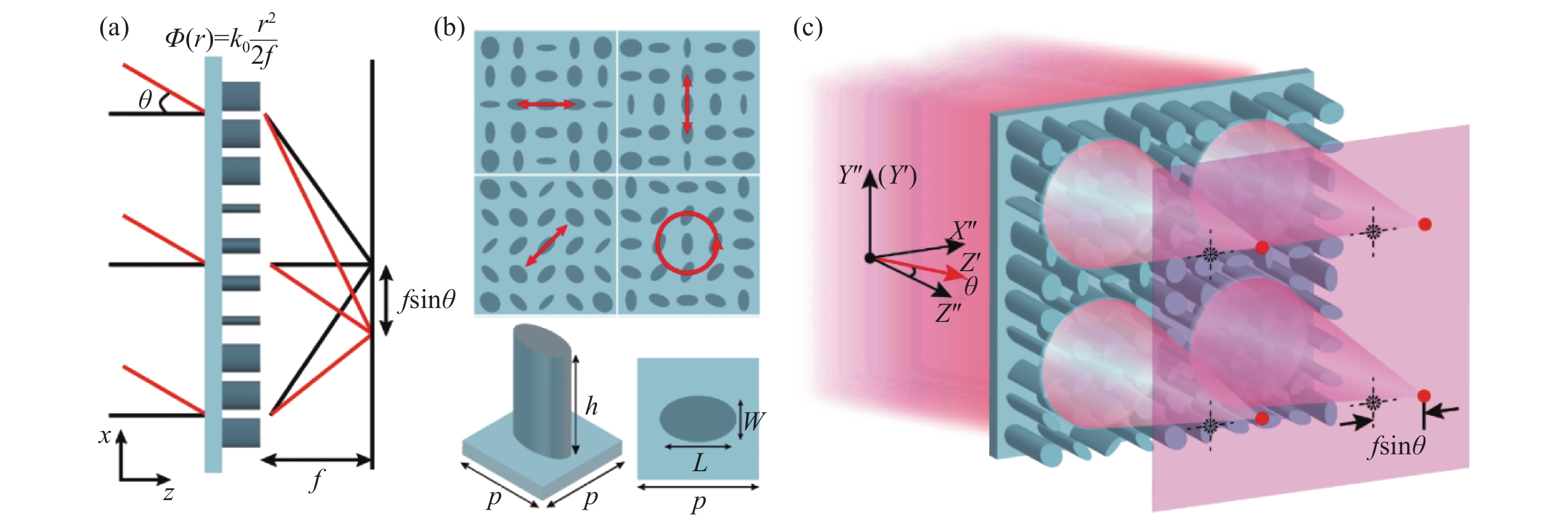
Fig. 1. Schematic illustration of metasurface of the compact polarimetry for large field of view. (a) Schematic diagram of rotational-translational symmetry conversion with quadratic phase metasurface; (b) Designed metasurface. The upper one is the top view of the designed metasurface, and the lower picture is illustration of a unit cell; (c) 3D schematic of the compact polarimetry for large field of view
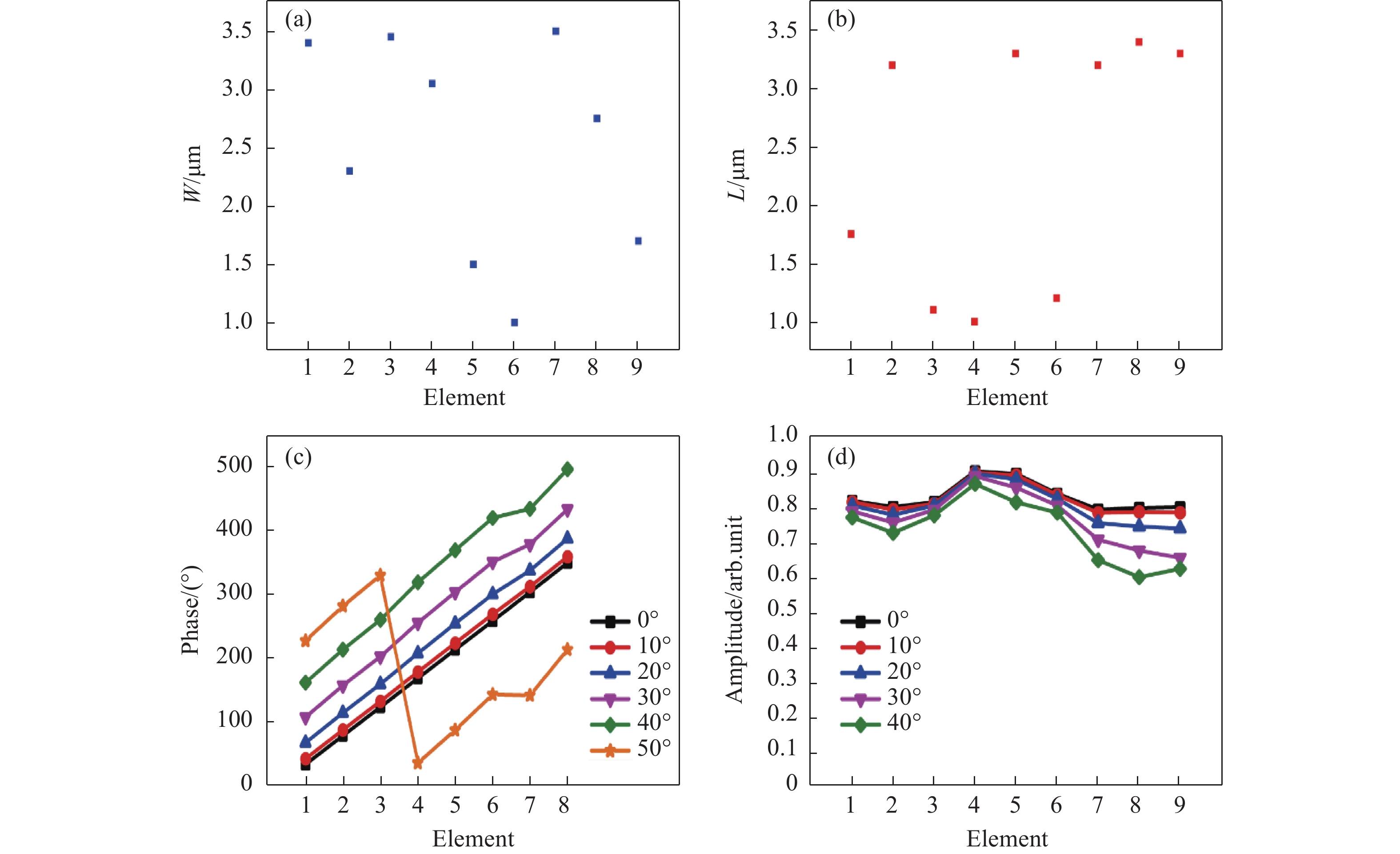
Fig. 2. Designed unit cells. (a), (b) Short axis (W ) and long axis (L ) dimensions of the optimized unit cells; (c) Corresponding phases response of the first eight elements for incident angles of 0°, 10°, 20°, 30°, 40°, and 50°, respectively; (d) Corresponding transmitted amplitudes of all elements for incident angles of 0°, 10°, 20°, 30°, and 40°, respectively
Fig. 3. Simulations verification of incident angle detection by the sub-array. (a) Focal focula intensity distribution at z =64 µm; (b) Calculated incident angles from Fig.3(a) and absolute errors
Fig. 4. Characterization results of the metasurface. (a), (b), and (c) Simulation results at incident angles of 0°, 20°, and 40°, respectively. The incident light from left to right corresponds to X , Y , A , B , L , and R polarization states. The upper rows of every illustration are facula distributions at the focal plane. The lower rows are calculated normalized Stokes parameters corresponding with the upper one
Fig. 5. Characterization of elliptically polarized light. (a) Diagram of intensity distributions at the focal plane; (b) Normalized Stokes parameters

Set citation alerts for the article
Please enter your email address
© Copyright 2018-2021 | Chinese Laser Press. All Rights Reserved 沪ICP备15018463号-20