
Jinliang Han, Jun Zhang, Xiaonan Shan, Hangyu Peng, Yawei Zhang, Lijun Wang, "High-power narrow-linewidth diode laser pump source based on high-efficiency external cavity feedback technology," Chin. Opt. Lett. 20, 081401 (2022)
- Chinese Optics Letters
- Vol. 20, Issue 8, 081401 (2022)
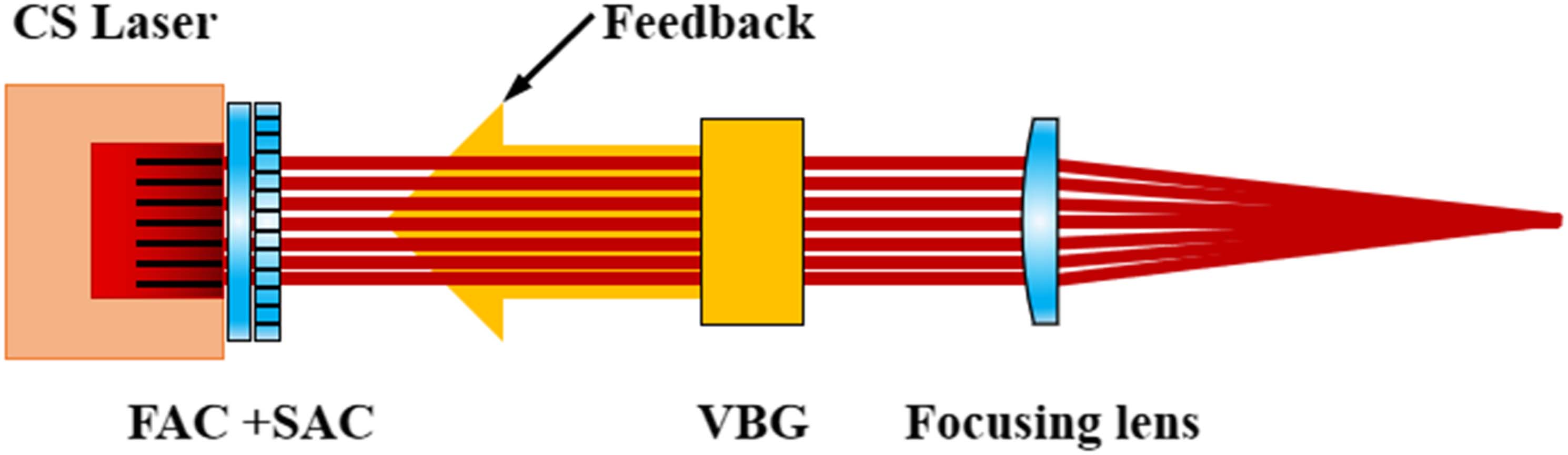
Fig. 1. External cavity feedback structure diagram based on FAC + SAC + VBG.
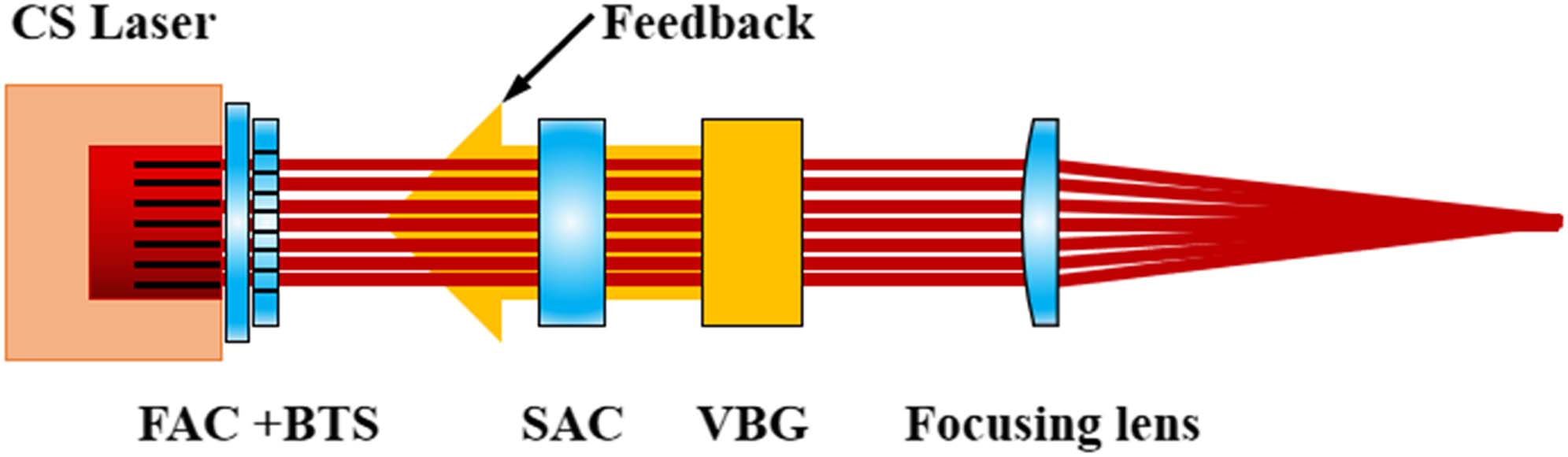
Fig. 2. External cavity feedback structure diagram based on FAC + BTS + SAC + VBG.
Fig. 3. Beam size and divergence angle after collimation of FAC + SAC + VBG external cavity structure.
Fig. 4. Effective feedback of FAC + SAC + VBG external cavity structure.
Fig. 5. Beam size and divergence angle after collimation of FAC + BTS + SAC + VBG external cavity structure.
Fig. 6. Effective feedback of FAC + BTS + SAC + VBG external cavity structure.
Fig. 7. Beam and divergence angle after collimation of FAC + BTS + SAC + VBG external cavity structure.
Fig. 8. Effective feedback of FAC + BTS + SAC + VBG external cavity structure.
Fig. 9. Simulation results of fast axis divergence angle.
Fig. 10. Simulation diagram based on FAC + BTS + SAC collimation structure.
Fig. 11. Simulation results of slow axis divergence angle and beam size.
Fig. 12. Simulation diagram of laser beam combination.
Fig. 13. Beam spot after optical fiber.
Fig. 14. Power–current–efficiency curve.
Fig. 15. Photograph of an 852 nm kW class narrow-linewidth laser.
Fig. 16. Laser spectrum at 35°C ± 5°C temperature control.
Fig. 17. Laser spectrum at (a) 25°C ± 5°C and (b) 50°C ± 5°C temperature control.
Fig. 18. Variation of central wavelength with operation time.
Fig. 19. Variation of spectral linewidth with operation time.
Fig. 20. Diagram of energy levels of cesium atoms.
|
Table 1. Typical Parameters of Laser Chip


Set citation alerts for the article
Please enter your email address

© Copyright 2018-2021 | Chinese Laser Press. All Rights Reserved 沪ICP备15018463号-20