• Acta Physica Sinica
  • Vol. 68, Issue 22, 220305-1 (2019)
Kai-Fa Luo and Rui Yu*
DOI: 10.7498/aps.68.20191398 Cite this Article
Kai-Fa Luo, Rui Yu. Topological states in electric circuit[J]. Acta Physica Sinica, 2019, 68(22): 220305-1 Copy Citation Text show less
The 1 D LC chain, in which a unit cell containing two inequivalent nodes A and B labeled by a dashed blue box. Each node A or B is grounded through a parallel connected inductor L and capacitor . All nodes are connected by and alternatively.一维SSH电路. 原胞(蓝色虚线框)内有A和B两个不等价节点, 经并联的电感L和电容接地. 原胞内节点由电容相连, 原胞间节点由电容相连
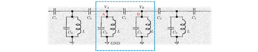
Fig. 1. The 1 D LC chain, in which a unit cell containing two inequivalent nodes A and B labeled by a dashed blue box. Each node A or B is grounded through a parallel connected inductor L and capacitor . All nodes are connected by and alternatively. 一维SSH电路. 原胞(蓝色虚线框)内有A和B两个不等价节点, 经并联的电感L和电容 接地. 原胞内节点由电容 相连, 原胞间节点由电容 相连
(a) Upper: increase the parameter of from zero to exceed , the end states (red) converge into the bulk states, indicating the topological transition. Bottom: the transition of winding number is consistent with the appearance and absence of end states. The effective polarization vector winds the original a round when the momentum varies continuously from 0 to for (left), while zero round for (right). (b) The electric potential distributions of two end states (green and puple) and a randomly selected bulk state (grey).(a) 上: 电容从0逐渐增加至超过, 频谱中两个端点态(红线)在能处消失, 表明系统发生了拓扑相变. 下: 系统缠绕数从1到0的跃变与端点态的消失临界值一致. 时系统的等效极化矢量在平面上随动量参数k从0连续变到时绕原点一周. 红圈对应缠绕数为1; 时绕原点0圈. 黑色圈对应缠绕数为0. (b) 取, 端点态(绿色和紫色)以及一个随机挑选的体态(灰色)对应的电势分布V
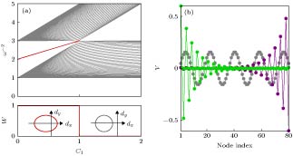
Fig. 2. (a) Upper: increase the parameter of from zero to exceed , the end states (red) converge into the bulk states, indicating the topological transition. Bottom: the transition of winding number is consistent with the appearance and absence of end states. The effective polarization vector winds the original a round when the momentum varies continuously from 0 to for (left), while zero round for (right). (b) The electric potential distributions of two end states (green and puple) and a randomly selected bulk state (grey). (a) 上: 电容 从0逐渐增加至超过 , 频谱中两个端点态(红线)在能 处消失, 表明系统发生了拓扑相变. 下: 系统缠绕数从1到0的跃变与端点态的消失临界值一致. 时系统的等效极化矢量在 平面上随动量参数k从0连续变到 时绕原点一周. 红圈对应缠绕数为1; 时 绕原点0圈. 黑色圈对应缠绕数为0. (b) 取 , 端点态(绿色和紫色)以及一个随机挑选的体态(灰色)对应的电势分布V
Schematic setup of the 3 D LC circuit lattice. (a) LC honeycomb layers stacked along c-direction without any interlayer connection. Two inequivalent nodes A and B within a unit cell, linked by capacitors . Each node A(B) is grounded through the parallel connected inductor () and capacitor (). a, b, and c denote lattice vectors. Inset: spectra of a single layer LC lattice includes two band-crossing points, extended uniformly along -direction and form two straight nodal lines (red) in the BZ. (b) Connecting nodes A and B between the nearest neighbor-layers with . The straight lines could be curved to a closed ring given appropriate . (c) Connect node-pairs A-A(B-B) between the nearest neighbor-layers with (), to break space inversion symmetry by setting and , and the nodal ring may be degenerated to discrete Weyl points. The LC network can be deformed into (d), which is convenient to construct circuit elements in experiments while spectrum invariant.三维LC电路示意图. (a) 单层LC蜂窝电路沿c方向上无连接的堆叠起来, 每个原胞内的两个不等价节点A和B在层内由连接. 每个节点都通过并联的和回路接地. a, b和c表示格矢. 小图: 单层LC电路频谱中包含两个简并点, 沿着方向扩展将在布里渊区中形成两条直线状的结线(红线). (b) 电容连接最近邻层间的节点A和B, 结线在给定合适的时将弯曲成闭合环形. (c) 电容连接最近邻层间的A-A(B-B)节点对, 且时空间反演对称破缺, 环状结线可能退化成离散的外尔点. 此外, LC网络可以变形成(d), 简化实验装置的同时保证频谱不变
Fig. 3. Schematic setup of the 3 D LC circuit lattice. (a) LC honeycomb layers stacked along c-direction without any interlayer connection. Two inequivalent nodes A and B within a unit cell, linked by capacitors . Each node A(B) is grounded through the parallel connected inductor ( ) and capacitor ( ). a, b, and c denote lattice vectors. Inset: spectra of a single layer LC lattice includes two band-crossing points, extended uniformly along -direction and form two straight nodal lines (red) in the BZ. (b) Connecting nodes A and B between the nearest neighbor-layers with . The straight lines could be curved to a closed ring given appropriate . (c) Connect node-pairs A-A(B-B) between the nearest neighbor-layers with ( ), to break space inversion symmetry by setting and , and the nodal ring may be degenerated to discrete Weyl points. The LC network can be deformed into (d), which is convenient to construct circuit elements in experiments while spectrum invariant. 三维LC电路示意图.  (a) 单层LC蜂窝电路沿c方向上无连接的堆叠起来, 每个原胞内的两个不等价节点A和B在层内由 连接. 每个节点 都通过并联的 和 回路接地. a, bc表示格矢. 小图: 单层LC电路频谱中包含两个简并点, 沿着 方向扩展将在布里渊区中形成两条直线状的结线(红线). (b) 电容 连接最近邻层间的节点AB, 结线在给定合适的 时将弯曲成闭合环形. (c) 电容 连接最近邻层间的A-A(B-B)节点对, 且 时空间反演对称破缺, 环状结线可能退化成离散的外尔点. 此外, LC网络可以变形成(d), 简化实验装置的同时保证频谱不变
(a) Nodal line (red) and its projections (grey) on the (001), (010), and (100) planes. The parameters are set as , and . (b) Bands along Γ-M-A-Y-B-M-Γ, where A and B are two points with on the nodal line as labeled in (a). Upper: the bulk bands(grey) with the drumhead-like surface states nestled inside the projection of the nodal ring (red) on the (001) surface and the two bands (purple) in periodic boundary condition. Bottom: the Berry phase equals π(0) inside (outside) the nodal ring.(a) 结线(红色)及其在(001), (010)和(100) 面上的投影(灰色). 此时参数取为和. (b) 沿Γ-M-A-Y-B-M-Γ路径的频谱, 其中A和B是(a)中结线与平面的交点. 上: (001) 方向的体态(灰色)及表面态(红线), 以及周期边界条件下的能带(紫色). 下: 积分路径在结线内部(外部)的贝里相位等于拓扑非平庸的π(平庸的0)
Fig. 4. (a) Nodal line (red) and its projections (grey) on the (001), (010), and (100) planes. The parameters are set as , and . (b) Bands along Γ-M-A-Y-B-M-Γ, where A and B are two points with on the nodal line as labeled in (a). Upper: the bulk bands(grey) with the drumhead-like surface states nestled inside the projection of the nodal ring (red) on the (001) surface and the two bands (purple) in periodic boundary condition. Bottom: the Berry phase equals π(0) inside (outside) the nodal ring. (a) 结线(红色)及其在(001), (010)和(100) 面上的投影(灰色). 此时参数取为 和 . (b) 沿Γ-M-A-Y-B-M-Γ路径的频谱, 其中AB是(a)中结线与 平面的交点. 上: (001) 方向的体态(灰色)及表面态(红线), 以及周期边界条件下的能带(紫色). 下: 积分路径在结线内部(外部)的贝里相位 等于拓扑非平庸的π(平庸的0)
(a) Four Weyl points in the Brillouin zone and their projections on (001), (010) and (100) direction. , , and are used in the calculations. The other parameters are the same as Fig.4. The Weyl points are the intersection points between the nodal ring determined by and the two planes determined by . The chirality are indicated as blue stars (red points) for (). (b) upper left: on the (001) surface, Fermi arcs connect the projections of the bulk Weyl nodes carrying opposite chiralities onto the surface. Upper right: the gapless surface band in the path. Dashed green line denotes the frequency where Weyl points lie. Bottom left: the Chern numbers for planes perpendicular to . Moving along , the Chern number increases (decreases) when the plane passing through the Weyl points with +1(–1) chirality(a) 布里渊区中的四个外尔点及它们在(001), (010)和(100)方向的投影. 取, 和, 其它参数均与图4中相同. 外尔点是由决定的结线与决定的两平面的交点, 它们的手性用蓝色五角星()和红色圆点()标记. (b) 左上: 在 (001) 表面上, 费米弧连接了手性相反外尔点的投影点. 右上: 开边界时路径AB上(亮青色虚线)的无能隙表面态, 绿色虚线标记外尔点所在频率. 左下: 垂直于的各平面上的陈数. 沿方向移动, 经过正(负)手性外尔点时平面上的陈数会增加1(减少1)
Fig. 5. (a) Four Weyl points in the Brillouin zone and their projections on (001), (010) and (100) direction. , , and are used in the calculations. The other parameters are the same as Fig.4. The Weyl points are the intersection points between the nodal ring determined by and the two planes determined by . The chirality are indicated as blue stars (red points) for ( ). (b) upper left: on the (001) surface, Fermi arcs connect the projections of the bulk Weyl nodes carrying opposite chiralities onto the surface. Upper right: the gapless surface band in the path. Dashed green line denotes the frequency where Weyl points lie. Bottom left: the Chern numbers for planes perpendicular to . Moving along , the Chern number increases (decreases) when the plane passing through the Weyl points with +1(–1) chirality (a) 布里渊区中的四个外尔点及它们在(001), (010)和(100)方向的投影. 取 , 和 , 其它参数均与图4中相同. 外尔点是由 决定的结线与 决定的两平面的交点, 它们的手性用蓝色五角星( )和红色圆点( )标记. (b) 左上: 在 (001) 表面上, 费米弧连接了手性相反外尔点的投影点. 右上: 开边界时路径AB上(亮青色虚线)的无能隙表面态, 绿色虚线标记外尔点所在频率. 左下: 垂直于 的各平面上的陈数. 沿 方向移动, 经过正(负)手性外尔点时平面上的陈数会增加1(减少1)
The band gap, as a function of the tolerance values for a super cell, where N is the number of total bands. The parameters are the same as Fig.5 in ideal case. Each range of tolerance is calculated 100 times. Numerical results show that Weyl points survive for ranges less than the critical value 30%. Inset: the bands along the k-path crossing two Weyl points with 20% range of tolerance on the capacitors.超胞的能隙随误差幅度的变化, 其中N是能带条数. 参数同图5理想情形. 每种误差幅度随机重复计算100次. 数值计算中误差幅度不超过30%时外尔点仍然存在. 小图为电容误差幅度为时两个外尔点所在路径的色散
Fig. 6. The band gap, as a function of the tolerance values for a super cell, where N is the number of total bands. The parameters are the same as Fig.5 in ideal case. Each range of tolerance is calculated 100 times. Numerical results show that Weyl points survive for ranges less than the critical value 30%. Inset: the bands along the k-path crossing two Weyl points with 20% range of tolerance on the capacitors. 超胞的能隙 随误差幅度的变化, 其中N是能带条数. 参数同图5理想情形. 每种误差幅度随机重复计算100次. 数值计算中误差幅度不超过30%时外尔点仍然存在. 小图为电容误差幅度为 时两个外尔点所在路径的色散
Kai-Fa Luo, Rui Yu. Topological states in electric circuit[J]. Acta Physica Sinica, 2019, 68(22): 220305-1
Download Citation