
Yanyi Wang, Kaihui Wang, Wen Zhou, Jianjun Yu. Photonic aided vector millimeter-wave signal generation without digital-to-analog converter[J]. Chinese Optics Letters, 2021, 19(1): 011101
- Chinese Optics Letters
- Vol. 19, Issue 1, 011101 (2021)
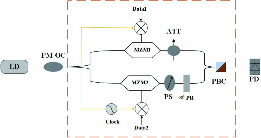
Fig. 1. Schematic diagram of the proposed scheme. LD, laser diode; PM-OC, polarization maintaining optical coupler; ATT, attenuator; PS, phase shifter;
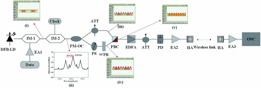
Fig. 2. Experimental setup of the proposed scheme. DFB-LD, distributed feedback laser diode; IM, intensity modulator; EA, electrical amplifier; PM-OC, polarization maintaining optical coupler; ATT, attenuator; PS, phase shifter;
Fig. 3. Received electric mm-wave signal spectra and constellation diagrams for the BTB and wireless transmission: (a) BTB transmission, (b) 1 m wireless transmission. (a1), (b1) Received mm-wave signal spectra, (a2), (b2) before orthogonalization, (a3), (b3) after orthogonalization, (a4), (b4) after CMA, (a5), (b5) after FOE, and (a6), (b6) after CPE.
Fig. 4. BER versus the optical power into the PD for BTB and wireless transmission.

Set citation alerts for the article
Please enter your email address
© Copyright 2018-2021 | Chinese Laser Press. All Rights Reserved 沪ICP备15018463号-20