
Yanyi Wang, Kaihui Wang, Wen Zhou, Jianjun Yu. Photonic aided vector millimeter-wave signal generation without digital-to-analog converter[J]. Chinese Optics Letters, 2021, 19(1): 011101
- Chinese Optics Letters
- Vol. 19, Issue 1, 011101 (2021)
Abstract
1. Introduction
With the advantages of large available bandwidth and small wireless interference, millimeter-wave (mm-wave) can be widely used in 5G/6G communication systems[
Meanwhile, in order to improve the spectral efficiency and the transmission rate in mm-wave communication systems, vector high-order modulation is deployed. In Ref. [21], by using an on–off-keying (OOK) baseband signal, the 4-ary quadrature amplitude modulation (4-QAM) mm-wave signal is generated. However, the method mentioned in Ref. [21] is complex and costly. Instead, the external modulator is employed to realize vector mm-wave signal generation with the aid of photonic frequency multiplication and pre-coding techniques or without precoding[
In this Letter, we proposed a novel and simple scheme of photonic aided vector mm-wave signal generation without a DAC. In our scheme, two intensity modulators (IMs) are utilized, one of which is driven by the baseband signal to generate an optical signal carrying data, and the other operates at its maximum transmission point (MATP) and is driven by a clock signal to generate two second-order optical subcarriers. The experiment results demonstrate that the bit error rate (BER) of the 20 Gb/s 4-QAM mm-wave signal can reach below the hard-decision forward-error-correction (HD-FEC) threshold of after a delivery over 1 m wireless distance. Based on our proposed scheme, we can generate high-speed vector mm-wave signals without a DAC, and it can reduce the system cost. Besides, the system based on our scheme can be integrated by using photonic technology to simplify the system structure effectively. We believe that our proposed scheme has potential applications in future high-speed optical communication.
Sign up for Chinese Optics Letters TOC. Get the latest issue of Chinese Optics Letters delivered right to you!Sign up now
2. Principle
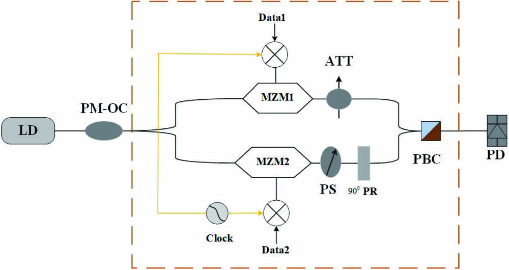
The schematic diagram of our proposed scheme is shown in Fig. 1. As shown in Fig. 1, the system is composed of a laser diode (LD), two Mach–Zehnder modulators (MZMs), a polarization maintaining optical coupler (PM-OC), a polarization beam combiner (PBC), an attenuator (ATT), a phase shifter (PS), a polarization rotator (PR), and a photodiode (PD). The optical signal from the LD is split into two paths by a PM-OC, and the two paths are modulated by two MZMs, respectively. The baseband data-1 mixed clock signal is used to drive MZM1, and the baseband data-2 mixed clock signal is used to drive MZM2, respectively. The PS is used to generate phase shifting between the two paths, and the PR makes sure that the two paths are orthogonal. The ATT is introduced to ensure that the output from two arms is equal to each other. Then, the two paths’ optical signals are combined via a PBC. Finally, the combined optical signal is sent into the PD, according to square detection law of the PD, and the vector mm-wave signal is generated after the PD. In the traditional vector mm-wave signal generation system, the DAC is indispensable[
![]()
Figure 1.Schematic diagram of the proposed scheme. LD, laser diode; PM-OC, polarization maintaining optical coupler; ATT, attenuator; PS, phase shifter;
The continuous wave (CW) with a carrier frequency of generated by the LD is split into two paths by a PM-OC and modulated by the two MZMs, respectively. The two baseband signals and are mixed with the RF signal generated by the clock source with a frequency of and then used to drive the two MZMs, respectively. The output of the MZMs can be expressed as
For the lower path, by using the PS, there is a phase difference compared to the upper path. So, the lower path can be written as
After the PD, we can obtain
When both of the input data and are M-ray amplitude-shift keying (M-ASK) signals, we can obtain an -QAM signal. Especially, if and are OOK signals, the received signal is a 4-QAM signal.
3. Experiment Results and Discussion
Figure 2 shows the experimental setup of our proposed scheme, which is a bit different from the schematic diagram. We used IM-1 and IM-2 to generate the modulated optical signal as denoted above, and the modulated optical signal is split into two paths by the PM-OC. Because the modulated optical signal from IM-2 can be split into two paths, to simplify the experimental setup, we used one baseband signal instead of two baseband signals, so the two baseband signals are identical. A 1552.2 nm light wave is emitted from a distributed feedback LD (DFB-LD) with a power of 15 dBm and then sent to IM-1 with 15 GHz bandwidth. A 10 Gb/s OOK baseband signal generated from a pseudo-random binary sequence (PRBS) pattern generator is amplified by an electrical amplifier (EA1) to drive the IM-1. The EA1 has a bandwidth of 15 GHz and an output power of 5Vpp. The output power from IM-1 is 1.2 dBm, and inset (i) in Fig. 2 shows the optical eye diagram of the optical baseband signal generated after IM-1. Then, the optical signal is fed into IM-2 with the bandwidth of 30 GHz. The IM-2 works at its MATP and is driven by a 20 GHz clock signal. The clock signal has a power of 20 dBm. The output power of IM-2 is −7.5 dBm. The optical spectrum after IM-2 modulation is shown in inset (ii) in Fig. 2. According to inset (ii) in Fig. 2, the frequency spacing between the generated second-order subcarrier and the optical center carrier is 40 GHz. After the PM-OC, the output optical signal from IM-2 is split into two paths. The PS is used to tune the phase difference between the upper and lower paths denoted as in Eq. (7). The ATT is used to adjust the optical power from the upper and lower paths to make sure that they are equal to each other. Insets (iii) and (iv) in Fig. 2 show the optical eye diagrams of the upper and lower paths, respectively. Then, the two paths are combined by a PBC with an output power of −10 dBm. Inset (v) in Fig. 2 shows the optical eye diagram after the PBC. The optical signal is amplified by an erbium-doped fiber amplifier (EDFA) and delivered into an ATT to adjust the optical power. Finally, the optical signal is detected by the 70 GHz bandwidth PD. So, the 40 GHz 4-QAM mm-wave signal is generated and amplified by EA2 with a bandwidth of 60 GHz and a gain of 30 dB. At the wireless transmitting side, the Q-band antenna (HA) with a gain of 25 dBi is placed to emit 40 GHz 4-QAM mm-wave signal. After HA, the electric mm-wave signal is transmitted over 1 m wireless distance.
![]()
Figure 2.Experimental setup of the proposed scheme. DFB-LD, distributed feedback laser diode; IM, intensity modulator; EA, electrical amplifier; PM-OC, polarization maintaining optical coupler; ATT, attenuator; PS, phase shifter;
At the wireless receiver, the electric mm-wave signal is firstly amplified by EA3 with a 60 GHz bandwidth. Next, the electric mm-wave signal is captured by a real-time digital storage oscilloscope (OSC). The OSC has 62 GHz bandwidth and 160 GSa/s sampling rate. Finally, in order to recover the 4-QAM signal, offline digital signal processing (DSP) is adopted.
Figures 3(a) and 3(b) show the received mm-wave signal electric spectra and constellation diagrams for back to back (BTB) and wireless transmission, respectively, when the optical power into the PD is −4 dBm. As shown in Fig. 3(a) or 3(b), the frequency of the received electric mm-wave signal is 40 GHz. From the constellation diagrams, the 4-QAM mm-wave signal is recovered and demodulated after a series of DSP, including orthogonalization, constant modulus algorithm (CMA) equalization, frequency offset estimation (FOE), and carrier phase estimation (CPE)[
![]()
Figure 3.Received electric mm-wave signal spectra and constellation diagrams for the BTB and wireless transmission: (a) BTB transmission, (b) 1 m wireless transmission. (a1), (b1) Received mm-wave signal spectra, (a2), (b2) before orthogonalization, (a3), (b3) after orthogonalization, (a4), (b4) after CMA, (a5), (b5) after FOE, and (a6), (b6) after CPE.
We calculated the BER curves versus the optical power for the 40 GHz 4-QAM signal BTB transmission and 1 m wireless transmission, respectively, as shown in Fig. 4 where the BTB and 1 m wireless transmission can reach the HD-FEC threshold of . The BER is improved with the increase of the optical power into the PD.
![]()
Figure 4.BER versus the optical power into the PD for BTB and wireless transmission.
When the optical power into the PD is increased by 1 dB, the BER (log) is reduced by 0.82 and 0.4 for BTB and 1 m wireless transmission, respectively. It is obvious that the BER curve is similar for BTB and wireless transmission. Moreover, in the condition of the same optical power into the PD, the BER (log) of the wireless transmission is large compared with the BTB transmission. When the BER (log) is decreased by one, the optical power into the PD increases by about 1.5 and 2 dB for BTB and 1 m wireless transmission, respectively. It can be concluded that the BER improves with the increasing optical power into the PD. The wireless transmission performance is worse than the BTB transmission performance due to the power penalty.
4. Conclusion
A novel scheme of photonic aided vector mm-wave signal generation without a DAC is proposed and experimentally demonstrated. The experimental results prove the feasibility of our proposed scheme. Based on this scheme, a 20 Gb/s 40 GHz vector mm-wave signal is generated without a DAC, which reduces the system cost significantly. By employing integrated photonic technology, the system structure can be simplified and easily implemented. We believe that the scheme has potential applications in future high-speed optical communication.
References
[2] S. Clark, H. Durrant-Whyte. Autonomous land vehicle navigation using millimeter wave radar, 3697(1998).
[5] P. Wu, J. Ma. Opt. Commun., 374, 69(2016).
[9] X. Li, J. Xiao, Y. Xu, L. Chen, J. Yu. Frequency-doubling photonic vector millimeter-wave signal generation from one DML. IEEE Photon. J., 7, 5501207(2015).
[12] X. Li, Z. Dong, J. Yu, N. Chi, Y. Shao, G. K. Chang. Fiber wireless transmission system of 108-Gb/s data over 80-km fiber and 2 × 2 MIMO wireless links at 100 GHz W-band frequency. Opt. Lett., 37, 5106(2012).
[23] X. Li, J. Yu, J. Xiao, N. Chi, Y. Xu. W-band PDM-QPSK vector signal generation by MZM-based photonic frequency octupling and precoding. IEEE Photon. J., 7, 7101906(2015).
[25] X. Li, J. Yu, J. Xiao, F. Li, Y. Xu, N. Chi, G. K. Chang. Mm-wave vector signal generation and transport for W-band MIMO system with intensity modulation and direct detection(2016).
[26] X. Li, J. Xiao, Y. Wang, Y. Xu, L. Chen, J. Yu. W-band QPSK vector signal generation based on photonic heterodyne beating and optical carrier suppression(2016).
[27] J. Xiao, Z. Zhang, X. Li, Y. Xu, L. Chen, J. Yu. High-frequency photonic vector signal generation employing a single phase modulator. IEEE Photon. J., 7, 7101206(2015).
[29] Y. Li, Y. Chen, W. Zhou, X. Tang, J. Shi, L. Zhao, J. Yu, G. K. Chang. D-band mm-wave SSB vector signal generation based on cascaded intensity modulators. IEEE Photon. J., 12, 7201111(2020).
[30] X. Pan, X. Liu, H. Zhang, C. Wang, X. Wang, Y. Zhang, D. Ran. Photonic vector mm-wave signal generation by optical dual-SSB modulation and a single push-pull MZM. Opt. Lett., 44, 3570(2019).
[31] W. Zhou, L. Zhao, J. Zhang, K. Wang. Four sub-channel single sideband generation of vector mm-wave based on an I/Q modulator. IEEE Photon. J., 11,, 7204409(2019).
[32] D. Wang, L. Xi, X. Tang. Photonic filterless scheme to generate V-band OFDM vector mm-wave signal without precoding. Opt. Commun., 466, 125663(2020).
[33] Y. Huang, J. Yu. Low complexity QPSK/8QAM millimeter-wave signal generation at D-band without phase pre-coding. Opt. Commun., 474, 126062(2020).
[34] J. Ma, A. Wen, W. Zhang. Carrier-frequency-doubled photonic microwave vector signal generation based on PDM-MZM. Opt. Commun., 450, 347(2019).
[35] J. Ma, A. Wen, C. Qiu. Photonic generation of microwave dual-band phase coded signal. Opt. Commun., 466, 125522(2020).
[36] D. Wang. V-band vector mm-wave signal generation enabled by a dual-parallel Mach-Zehnder modulator without precoding and optical filter. Microwave Opt. Technol. Lett., 62, 3412(2020).
[37] D. Wang, X. Tang, L. Xi. A filterless scheme of generating frequency 16-tupling millimeter-wave based on only two MZMs. Opt. Laser Technol., 116, 7(2019).
[38] L. Zhao, L. Xiong, M. Liao. W-band 8QAM vector millimeter-wave signal generation based on tripling of frequency without phase pre-coding. IEEE Access, 7, 156978(2019).
[39] J. Xiao, X. Feng, W. Zhou. Generation of (3, 1) vector signals based on optical carrier suppression without pre-coding. Opt. Lett., 45, 1009(2020).
[40] J. Yu, X. Zhou. Ultra-high-capacity DWDM transmission system for 100G and beyond. Commun. Mag., 48, 56(2010).

Set citation alerts for the article
Please enter your email address
© Copyright 2018-2021 | Chinese Laser Press. All Rights Reserved 沪ICP备15018463号-20