• Acta Optica Sinica
  • Vol. 41, Issue 10, 1012004 (2021)
Le Wang1、2, Qian Zhou1, Yue Fang1, Shengchun Wang1、*, Hao Wang1, Guoqing Li1, Shengwei Ren1, Peng Dai1, Qiang Han1、3, and Fan Wang1
Author Affiliations
  • 1Infrastructure Inspection Research Institute, China Academy of Railway Sciences Corporation Limited, Beijing 100081, China
  • 2Graduate Department of China Academy of Railway Sciences, Beijing 100081, China
  • 3School of Science, Beijing Jiaotong University, Beijing 100044, China
  • show less
    DOI: 10.3788/AOS202141.1012004 Cite this Article Set citation alerts
    Le Wang, Qian Zhou, Yue Fang, Shengchun Wang, Hao Wang, Guoqing Li, Shengwei Ren, Peng Dai, Qiang Han, Fan Wang. Rail Longitudinal Calibration Method for Profile Measurement System[J]. Acta Optica Sinica, 2021, 41(10): 1012004 Copy Citation Text show less
    Geometric model of line structured light perspective projection
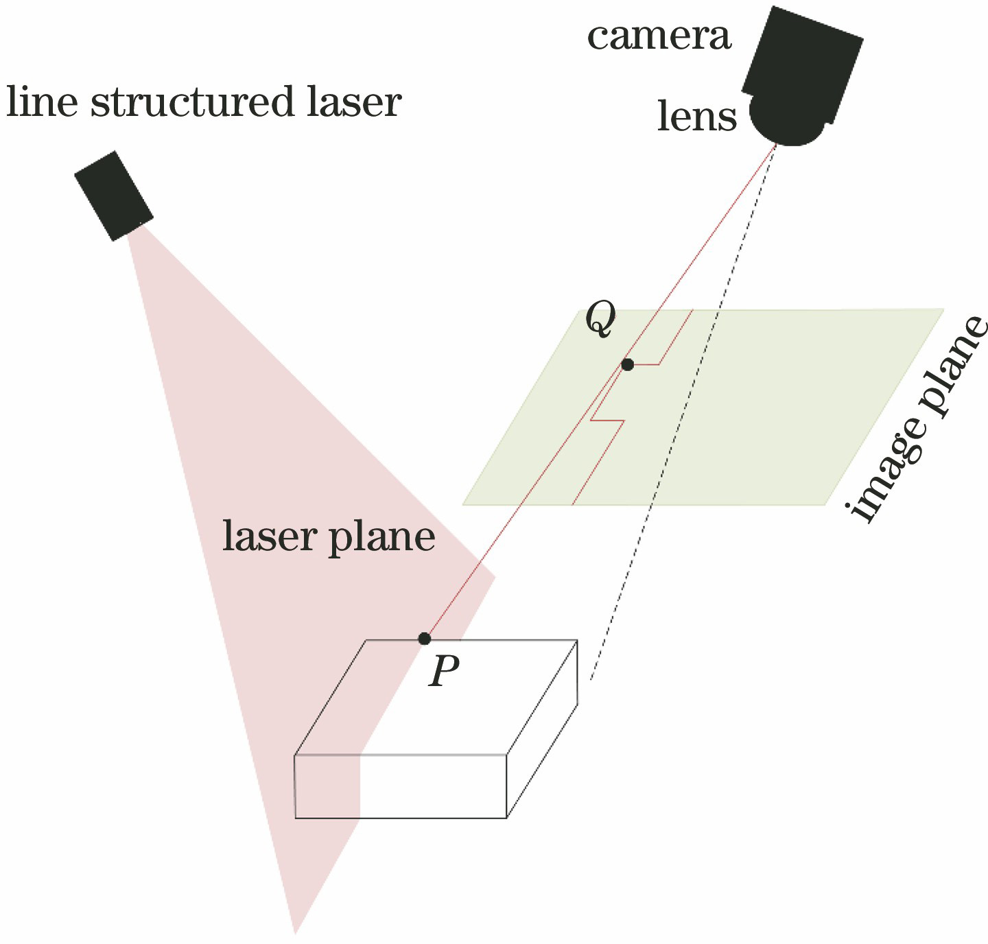
    Fig. 1. Geometric model of line structured light perspective projection
    Schematic diagram of rail profile measurement with line structured light
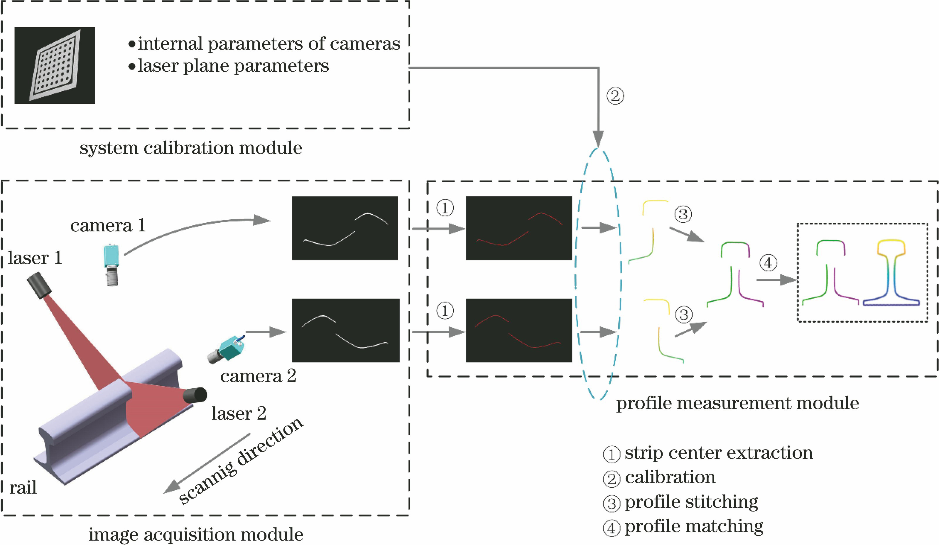
    Fig. 2. Schematic diagram of rail profile measurement with line structured light
    Target coordinate system and rail longitudinal direction. (a) Target coordinate system; (b) Z-axis (Ztcs) of target coordinate system is vertical to rail longitudinal direction
    Fig. 3. Target coordinate system and rail longitudinal direction. (a) Target coordinate system; (b) Z-axis (Ztcs) of target coordinate system is vertical to rail longitudinal direction
    Schematic diagrams of plane target moving on rail surface. (a) Longitudinal rotation around rail; (b) longitudinal translation along rail; (c) rotate around the Z-axis of target coordinate system tcs
    Fig. 4. Schematic diagrams of plane target moving on rail surface. (a) Longitudinal rotation around rail; (b) longitudinal translation along rail; (c) rotate around the Z-axis of target coordinate system tcs
    Diagrams of nine typical plane target poses
    Fig. 5. Diagrams of nine typical plane target poses
    Flow chart of rail longitudinal calibration
    Fig. 6. Flow chart of rail longitudinal calibration
    Rail profile measurement device with structured light. (a) Rail profile measurement device; (b) flat target is closely attached to top surface of rail; (c) flat target is closely attached to side of rail
    Fig. 7. Rail profile measurement device with structured light. (a) Rail profile measurement device; (b) flat target is closely attached to top surface of rail; (c) flat target is closely attached to side of rail
    Plane target images under different postures
    Fig. 8. Plane target images under different postures
    Distribution of vectors Vi and the normal of fitting plane
    Fig. 9. Distribution of vectors Vi and the normal of fitting plane
    Schematic diagrams of rail rotation position. (a) Axonometric view; (b) top view
    Fig. 10. Schematic diagrams of rail rotation position. (a) Axonometric view; (b) top view
    Rail longitudinal calibration results for 9 rotating positions
    Fig. 11. Rail longitudinal calibration results for 9 rotating positions
    Relationship between rail longitudinal calibration error and number of target images
    Fig. 12. Relationship between rail longitudinal calibration error and number of target images
    xi0.0020.150-0.009-0.0090.014-0.0110.7160.8330.7470.729
    yi0.0030.0400.0010.0010.00700.2140.2040.1840.182
    zi-0.999-0.988-0.999-0.999-0.999-1.000-0.664-0.515-0.638-0.660
    Table 1. Coordinates of vector Vi in world coordinate system
    Index12345678910
    Error /(°)0.050.030.060.020.030.030.040.030.040.05
    Table 2. Rail longitudinal calibration error
    Le Wang, Qian Zhou, Yue Fang, Shengchun Wang, Hao Wang, Guoqing Li, Shengwei Ren, Peng Dai, Qiang Han, Fan Wang. Rail Longitudinal Calibration Method for Profile Measurement System[J]. Acta Optica Sinica, 2021, 41(10): 1012004
    Download Citation