
Zhaojian Zhu, Ke Han, Hongliang Li, Qiang Zhu. Study on Microstructure and Properties of Inconel 690 Local Dry Underwater Laser Welded Joints[J]. Chinese Journal of Lasers, 2023, 50(16): 1602107
- Chinese Journal of Lasers
- Vol. 50, Issue 16, 1602107 (2023)
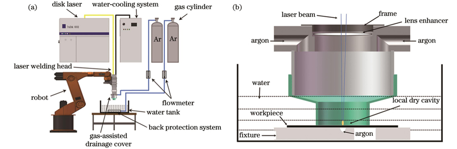
Fig. 1. Experimental system and device diagrams of underwater local dry laser welding. (a) Experimental system; (b) gas-assisted drainage device
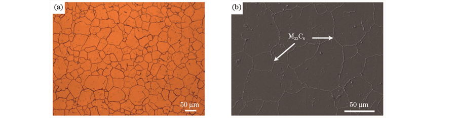
Fig. 2. Microstructure of Inconel 690. (a) OM photo; (b) SEM photo
Fig. 3. Sizes of samples for mechanical property test. (a) High temperature tensile sample; (b) normal temperature tensile sample; (c) Charpy impact sample
Fig. 4. Weld surface morphologies and sections under different heat inputs. (a) Front, (b) back, (c) section when heat input is 0.1500 kJ/mm; (d) front, (e) back, (f) section when heat input is 0.0750 kJ/mm; (g) front, (h) back, (i) section when heat input is 0.0500 kJ/mm; (j) section, (k) front, (l) back when heat input is 0.0375 kJ/mm; (m) section, (n) front, (o) back when heat input is 0.0300 kJ/mm; (p) section, (q) front, (r) back when heat input is 0.0250 kJ/mm
Fig. 5. Weld widths under different heat inputs
Fig. 6. OM photos of weld centers under different heat inputs. (a) 0.1500 kJ/mm; (b) 0.0750 kJ/mm; (c) 0.0500 kJ/mm; (d) 0.0375 kJ/mm; (e) 0.0300 kJ/mm
Fig. 7. OM photos of weld edges under different heat inputs. (a) 0.1500 kJ/mm; (b) 0.0750 kJ/mm; (c) 0.0500 kJ/mm; (d) 0.0375 kJ/mm; (e) 0.0300 kJ/mm
Fig. 8. Test results of mechanical properties of welded joints. (a) Tensile test under different heat inputs; (b) Charpy impact test under different welding speeds
Fig. 9. Weld surface morphologies and sections under different defocusing amounts. (a) Front, (b) back, and (c) section when defocusing amount is -4 mm; (d) section, (e) front, and (f) back when defocusing amount is -2 mm; (g) front, (h) back, and (i) section when defocusing amount is 2 mm; (j) section, (k) front, and (l) back when defocusing amount is 4 mm
Fig. 10. Weld widths under different defocus amounts
Fig. 11. Test results of mechanical properties of welded joints under different defocusing amounts. (a) Tensile test; (b) Charpy impact test
Fig. 12. Appearances and cross sections of welds. (a) Front, (b) back, and (c) section of onshore weld; (d) front, (e) back, and (f) section of underwater weld
Fig. 13. Microstructures of weld centers. (a) Onshore weld; (b) partial magnification of Fig. 13 (a); (c) underwater weld; (d) partial magnification of Fig. 13 (c)
Fig. 14. Line scan results of weld dendrites. (a) Onshore weld; (b) underwater weld
Fig. 15. Tensile test results of welded joints under different temperatures. (a) Room temperature; (b) 350 ℃
Fig. 16. Tensile fracture morphologies
Fig. 17. Impact fracture morphologies
Fig. 18. Microhardnesses of welded joints. (a) Transverse; (b) longitudinal
|
Table 1. Chemical compositions of Inconel 690 nickel-based alloy (mass fraction, %)
|
Table 2. Mechanical properties of Inconel 690 nickel-based alloy
|
Table 3. Process parameters under same defocusing amount
|
Table 4. Process parameters under same heat input

Set citation alerts for the article
Please enter your email address
© Copyright 2018-2021 | Chinese Laser Press. All Rights Reserved 沪ICP备15018463号-20