• Chinese Journal of Lasers
  • Vol. 50, Issue 4, 0402022 (2023)
Ye Ma1, Cheng Lei1、*, Ting Liang1、**, Pengfei Ji1, Yuqiao Liu1, Bingyan Wang2, and Guofeng Chen2
Author Affiliations
  • 1State Key Laboratory of Dynamic Measurement Technology, North University of China, Taiyuan 030051, Shanxi, China
  • 2Inner Mongolia Power Machinery Institute, Hohhot 010010, Inner Mongolia, China
  • show less
    DOI: 10.3788/CJL221348 Cite this Article Set citation alerts
    Ye Ma, Cheng Lei, Ting Liang, Pengfei Ji, Yuqiao Liu, Bingyan Wang, Guofeng Chen. Sapphire Through‐Hole Machining with 355 nm All‐Solid‐State Ultraviolet Nanosecond Laser[J]. Chinese Journal of Lasers, 2023, 50(4): 0402022 Copy Citation Text show less
    Schematic of ultraviolet micro machining system
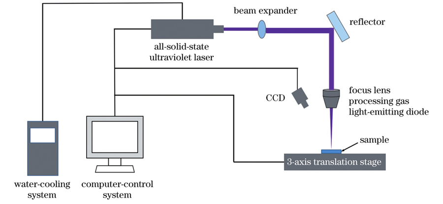
    Fig. 1. Schematic of ultraviolet micro machining system
    Schematics of laser machining. (a) Shock drilling; (b) rotary cutting and drilling; (c) spiral drilling
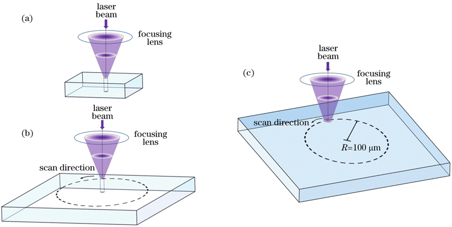
    Fig. 2. Schematics of laser machining. (a) Shock drilling; (b) rotary cutting and drilling; (c) spiral drilling
    SEM and 3D images of through-hole. (a) SEM image of through-hole surface; 3D images of (b) through-hole surface,
    Fig. 3. SEM and 3D images of through-hole. (a) SEM image of through-hole surface; 3D images of (b) through-hole surface,
    SEM images of through-holes processed under different energy densities. (a) 27.68 J/cm2; (b) 29.57 J/cm2; (c) 31.12 J/cm2;
    Fig. 4. SEM images of through-holes processed under different energy densities. (a) 27.68 J/cm2; (b) 29.57 J/cm2; (c) 31.12 J/cm2;
    Morphologies of sapphire through-holes processed under different laser repetition frequencies
    Fig. 5. Morphologies of sapphire through-holes processed under different laser repetition frequencies
    SEM image of drilling failure when energy density and repetition frequency of laser is 32.59 J/cm2 and 45 kHz, respectively
    Fig. 6. SEM image of drilling failure when energy density and repetition frequency of laser is 32.59 J/cm2 and 45 kHz, respectively
    Surface morphologies of sapphire micro through-holes processed under different laser scanning speeds
    Fig. 7. Surface morphologies of sapphire micro through-holes processed under different laser scanning speeds
    Cross-section SEM images and tapering angles of sapphire micro through-holes processed under different laser scanning speeds. (a) 0.9 mm/s; (b) 0.7 mm/s; (c) 0.5 mm/s; (d) 0.3 mm/s; (e) 0.1 mm/s; (f) through-hole tapering angle versus laser scanning speed
    Fig. 8. Cross-section SEM images and tapering angles of sapphire micro through-holes processed under different laser scanning speeds. (a) 0.9 mm/s; (b) 0.7 mm/s; (c) 0.5 mm/s; (d) 0.3 mm/s; (e) 0.1 mm/s; (f) through-hole tapering angle versus laser scanning speed
    Morphology image of sapphire through-hole under optimal parameter conditions. (a) SEM amplification image of through-hole edge; (b) three-dimensional image of through-hole morphology
    Fig. 9. Morphology image of sapphire through-hole under optimal parameter conditions. (a) SEM amplification image of through-hole edge; (b) three-dimensional image of through-hole morphology
    Laser parameterValue
    Wavelength355 nm
    Pulse width10-25 ns
    Frequency20-100 kHz
    Power0-300 μJ
    Spot modeTEM00(quality factor M2<1.3)
    Table 1. Main technical parameters of ultraviolet laser
    Laser pulse width /nsLaser repetition frequency /kHz
    1130
    1340
    1550
    1760
    1970
    Table 2. Relationship between laser pulse width and repetition frequency
    d /μmfREP /kHzvs /(mm·s-1η /%
    30300.199.99
    30300.399.97
    30300.599.94
    30300.799.92
    30300.999.90
    Table 3. Relationship between laser pulse overlap rate and scanning speed
    ParameterPresent workRef.[23Ref.[14Ref.[15
    MaterialMonocrystalline sapphire(c-cut)

    Monocrystalline sapphire

    (c-cut)

    Monocrystalline sapphire(c-cut)Monocrystalline sapphire(c-cut)
    Beam styleGaussianBesselGaussianGaussian
    Pulse duration

    Nanosecond

    (11-19 ns)

    Picosecond(6 ps)Picosecond(0.8 ps)

    Femtosecond

    (300-500 fs)

    Sample thickness500 μm430 μm300 μm430 μm
    Hole diameter~200 μm~100 μm~1 mm~400 μm
    Machining technique

    Up-bottom

    ablation with spiraling

    Trepanning with polyimide tape

    Bottom-up ablation

    with spiraling

    Bottom-up ablation

    with spiraling

    Tapering angle<5°<3°<2°-<5°
    Z-axis translationYesNoYesYes
    Table 4. Comparisons of sapphire through-holes processed by ultraviolet nanosecond laser with results in literatures
    Ye Ma, Cheng Lei, Ting Liang, Pengfei Ji, Yuqiao Liu, Bingyan Wang, Guofeng Chen. Sapphire Through‐Hole Machining with 355 nm All‐Solid‐State Ultraviolet Nanosecond Laser[J]. Chinese Journal of Lasers, 2023, 50(4): 0402022
    Download Citation