• Photonics Research
  • Vol. 9, Issue 5, 757 (2021)
Dajian Liu1, Long Zhang1, Hexin Jiang1, and Daoxin Dai1、2、*
Author Affiliations
  • 1State Key Laboratory for Modern Optical Instrumentation, Center for Optical & Electromagnetic Research, College of Optical Science and Engineering, International Research Center for Advanced Photonics, Zhejiang University, Hangzhou 310058, China
  • 2Ningbo Research Institute, Zhejiang University, Ningbo 315100, China
  • show less
    DOI: 10.1364/PRJ.420545 Cite this Article Set citation alerts
    Dajian Liu, Long Zhang, Hexin Jiang, Daoxin Dai. First demonstration of an on-chip quadplexer for passive optical network systems[J]. Photonics Research, 2021, 9(5): 757 Copy Citation Text show less
    (a) PON wavelength plan. US, upstream; DS, downstream; BW, bandwidth. (b) PON configuration with the coexistence of GPON and 10G GPON. (c) Structure schematic diagram of a quadplexer.
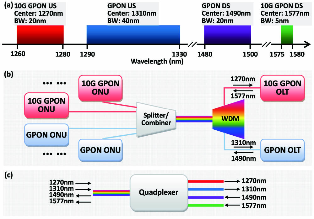
    Fig. 1. (a) PON wavelength plan. US, upstream; DS, downstream; BW, bandwidth. (b) PON configuration with the coexistence of GPON and 10G GPON. (c) Structure schematic diagram of a quadplexer.
    Schematic configurations: (a) proposed quadplexer; (b) MWG-based filter, consisting of a mode (de)multiplexer and an MWG-based filter; (c) mode (de)multiplexer based on an adiabatic dual-core taper; and (d) longitudinal apodization for the MWG.
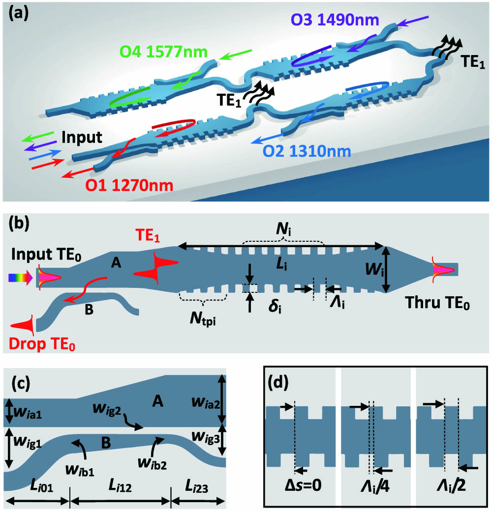
    Fig. 2. Schematic configurations: (a) proposed quadplexer; (b) MWG-based filter, consisting of a mode (de)multiplexer and an MWG-based filter; (c) mode (de)multiplexer based on an adiabatic dual-core taper; and (d) longitudinal apodization for the MWG.
    (a) Calculated dispersion curves of an SOI strip waveguide for the TE0 and TE1 modes at four wavelength bands (i.e., 1270, 1310, 1490, and 1577 nm). Simulated transmissions of the designed mode (de)multiplexer for the wavelength band of (b) 1270/1310 nm and the wavelength band of (c) 1490/1577 nm. Insets: simulated light propagation in the designed adiabatic taper.
    Fig. 3. (a) Calculated dispersion curves of an SOI strip waveguide for the TE0 and TE1 modes at four wavelength bands (i.e., 1270, 1310, 1490, and 1577 nm). Simulated transmissions of the designed mode (de)multiplexer for the wavelength band of (b) 1270/1310 nm and the wavelength band of (c) 1490/1577 nm. Insets: simulated light propagation in the designed adiabatic taper.
    Calculated transmittance spectra at the drop and through ports for the designed MWGs at the channels of (a) 1270, (b) 1310, (c) 1490, and (d) 1577 nm.
    Fig. 4. Calculated transmittance spectra at the drop and through ports for the designed MWGs at the channels of (a) 1270, (b) 1310, (c) 1490, and (d) 1577 nm.
    Simulated transmissions at the drop port of the designed MWG filter at the 1577 nm channel when assuming that there is some core-width variation (i.e., Δw=±10 nm and ±20 nm).
    Fig. 5. Simulated transmissions at the drop port of the designed MWG filter at the 1577 nm channel when assuming that there is some core-width variation (i.e., Δw=±10  nm and ±20  nm).
    (a) Microscope image of the fabricated quadplexers on silicon. SEM images of the grating couplers working around (b) 1300 nm and (c) 1530 nm, parts of gratings for (d) 1270 nm, (e) 1310 nm, (f) 1490 nm, and (g) 1577 nm.
    Fig. 6. (a) Microscope image of the fabricated quadplexers on silicon. SEM images of the grating couplers working around (b) 1300 nm and (c) 1530 nm, parts of gratings for (d) 1270 nm, (e) 1310 nm, (f) 1490 nm, and (g) 1577 nm.
    Measured spectral responses for the four channels of (a) 1270 nm, (b) 1310 nm, (c) 1490 nm, and (d) 1577 nm.
    Fig. 7. Measured spectral responses for the four channels of (a) 1270 nm, (b) 1310 nm, (c) 1490 nm, and (d) 1577 nm.
    (a) Measurement setup for the eye diagram, including tunable lasers, polarization controllers (PCs), Mach–Zehnder modulators (MZMs), pulse pattern generators (PPGs), an off-chip multiplexer (MUX), the device under test (DUT), an optical receiver (Recv.), and a digital communication analyzer (DCA). Measured eye diagrams for the channels of (b) 1271 nm, (c) 1311 nm, and (d) 1577 nm.
    Fig. 8. (a) Measurement setup for the eye diagram, including tunable lasers, polarization controllers (PCs), Mach–Zehnder modulators (MZMs), pulse pattern generators (PPGs), an off-chip multiplexer (MUX), the device under test (DUT), an optical receiver (Recv.), and a digital communication analyzer (DCA). Measured eye diagrams for the channels of (b) 1271 nm, (c) 1311 nm, and (d) 1577 nm.
    (a) Microscopy picture of the fabricated identical MWG-based filters; (b) measurement responses at the drop-port; (c) the central wavelength deviation and (d) the 3 dB bandwidth deviation among six samples.
    Fig. 9. (a) Microscopy picture of the fabricated identical MWG-based filters; (b) measurement responses at the drop-port; (c) the central wavelength deviation and (d) the 3 dB bandwidth deviation among six samples.
    Dajian Liu, Long Zhang, Hexin Jiang, Daoxin Dai. First demonstration of an on-chip quadplexer for passive optical network systems[J]. Photonics Research, 2021, 9(5): 757
    Download Citation