
Deen Wang, Xin Zhang, Wanjun Dai, Ying Yang, Xuewei Deng, Lin Chen, Xudong Xie, Dongxia Hu, Feng Jing, Zeping Yang, Qiang Yuan, Xiaofeng Wei, Qihua Zhu, Wanguo Zheng, Xiaomin Zhang, Lei Huang, "1178 J, 527 nm near diffraction limited laser based on a complete closed-loop adaptive optics controlled off-axis multi-pass amplification laser system," High Power Laser Sci. Eng. 9, 02000e22 (2021)
- High Power Laser Science and Engineering
- Vol. 9, Issue 2, 02000e22 (2021)
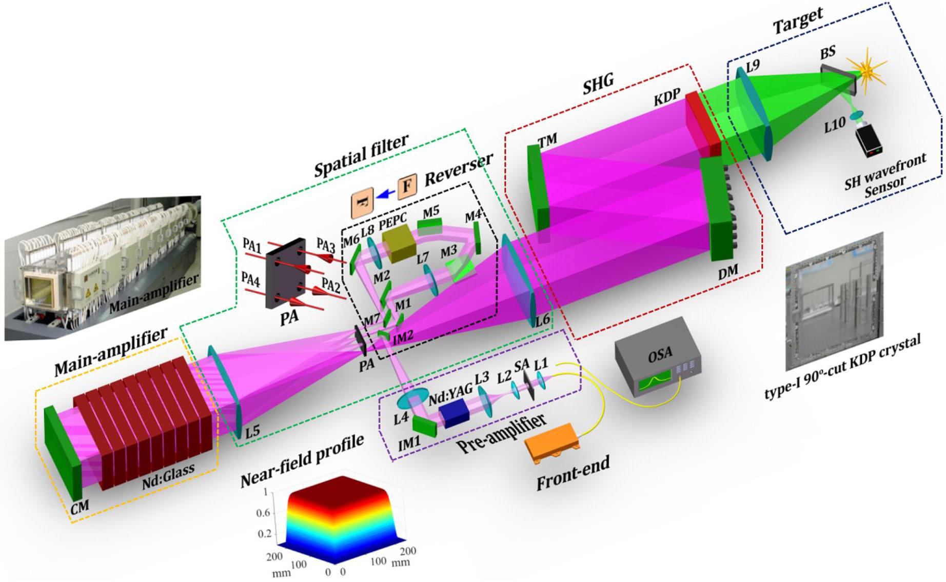
Fig. 1. Schematic diagram of the 1178 J near diffraction limited 527 nm laser system using off-axis multi-pass amplification and complete closed-loop AO. BS, beamsplitter; CM, cavity mirror; DM, deformable mirror; L1–L10, focus lenses; M1–M7, IM1 and IM2, reflection mirrors; OSA, optical spectrum analyzer; PA, pinhole array; PEPC, plasma-electrode Pockels cell; SA, square aperture; TM, transport mirror.
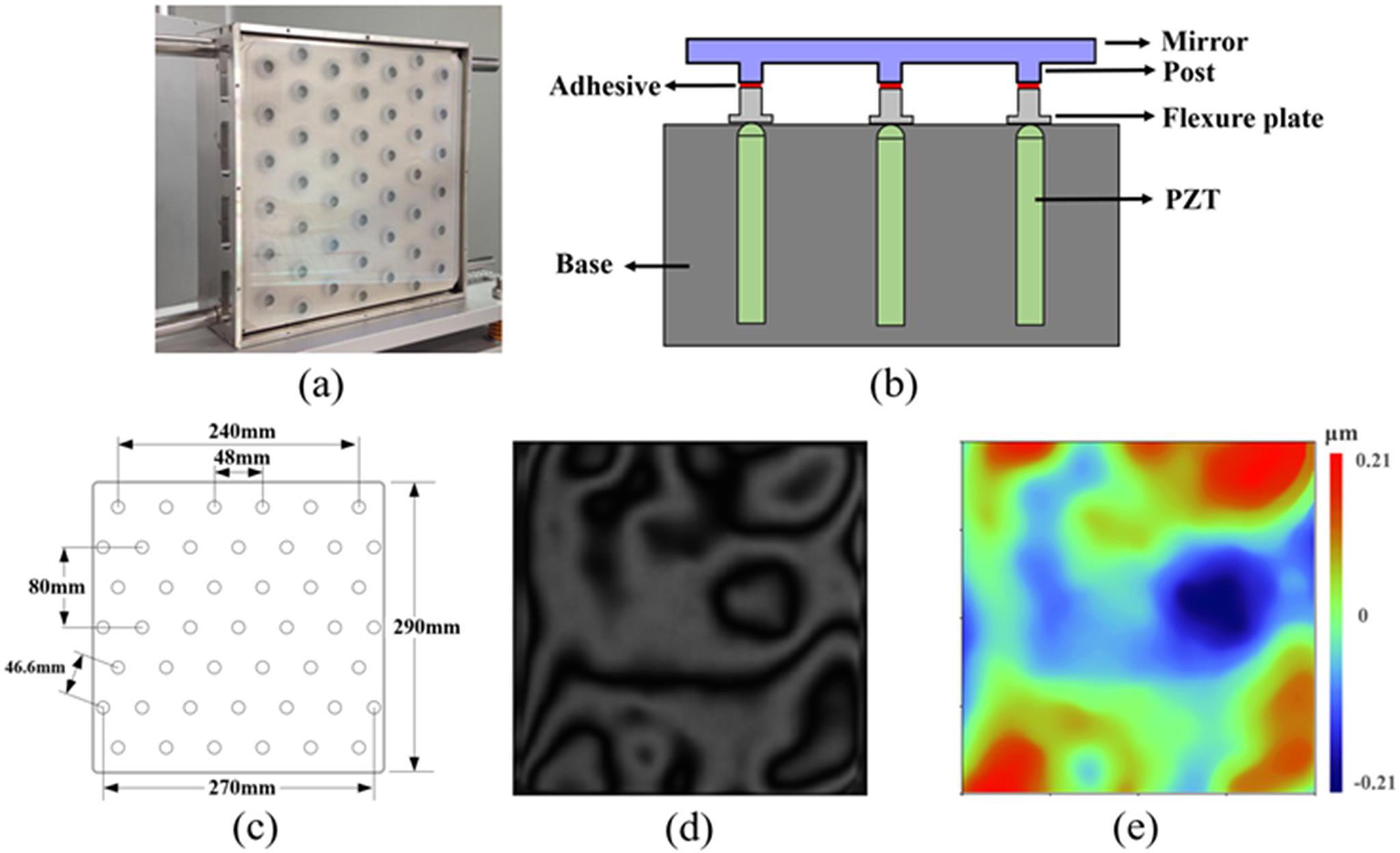
Fig. 2. (a) Photo and (b) schematic diagram of the lab-manufactured DM; (c) hexagonally distributed 45 actuators in the DM; (d) interference fringe and (e) wavefront of the initial surface shape of the DM.
Fig. 3. Optical schemes for configurations (a) C1 and (b) C2.
Fig. 4. (a), (c) Laser beam on the DM in configurations (a) C1 and (c) C2. (b), (d) Influence functions for the same actuator (i.e., the actuator in the blue dashed square in (a) and (c)) for configurations (b) C1 and (d) C2.
Fig. 5. Comparison between the representative eigenmodes of configurations C1 and C2. The first and third rows are for configuration C1 and the second and fourth rows are for configuration C2.
Fig. 6. Correction results of configurations C1 and C2 for the 3rd to 15th Zernike-mode aberrations: (a) PV and (b) RMS values of the residual errors.
Fig. 7. The 4th, 5th, 11th, and 12th Zernike modes.
Fig. 8. The target wavefront distortions to be corrected: (a) static wavefront distortion and (b) dynamic wavefront distortion.
Fig. 9. The wavefront distortions of the laser beam on the image plane before pinholes (a1) PA2, (b1) PA3, and (c1) PA4 and (d1) at the target; (a2)–(d2) are the corresponding distributions of the focal spots.
Fig. 10. (a), (b) Generated surface shapes of the DM to compensate the wavefront distortions for configurations C1 and C2, respectively; (c) residual wavefront error at the target after correction by using configuration C1; (d) distribution of the target focal spot after correction by using configuration C1.
Fig. 11. Residual errors of the wavefront distortions on the image plane before pinholes (a1) PA2, (b1) PA3, and (c1) PA4 and (d1) at the target after correction by using the configuration C2; (a2)–(d2) corresponding distributions of the focal spots.
Fig. 12. Experimental results: (a) static wavefront distortion of the entire beamline; (b) dynamic wavefront distortion of the main amplifier; (c) total wavefront distortion of the entire beamline composed of static and dynamic wavefront distortions; (d) residual error of the wavefront distortion at the target after correction; (e) distribution of the focal spot at the target before correction; (f) distribution of the focal spot at the target after correction.
Fig. 13. Measured wavefront distortion of the 527 nm laser at the target and the corresponding distribution of the focal spot for: (a1), (a2) the first shot; (b1), (b2) the second shot; (c1), (c2) the third shot.
|
Table 1. Parameters of the lenses.
|
Table 2. Parameters of the reflection mirrors.
|
Table 3. Parameters of the spatial filter pinholes.
|
Table 4. Key parameters of the lab-manufactured DM.
|
Table 5. Performance of the lab-manufactured DM.
|
Table 6. Residual errors and beam quality for three consecutive shots.


Set citation alerts for the article
Please enter your email address

© Copyright 2018-2021 | Chinese Laser Press. All Rights Reserved 沪ICP备15018463号-20