
Xin Wang, Sihua Yang. Imaging of human wrist joint by a flexible-transducer-based morphological-adaptive photoacoustic tomography: a feasibility study[J]. Chinese Optics Letters, 2019, 17(9): 091701
- Chinese Optics Letters
- Vol. 17, Issue 9, 091701 (2019)
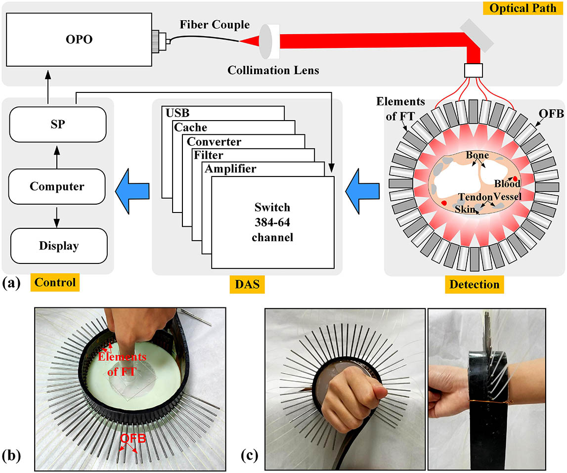
Fig. 1. (a) Schematic of the PAI system for joint imaging. FT, flexible transducer; DAS, data acquisition system; SP, synchronization pulse; OFBs, optical fiber bundles. (b) PAI joint interface for distal interphalangeal (DIP) joint imaging. (c) Front and side views of the PAI joint interface for wrist joint imaging.
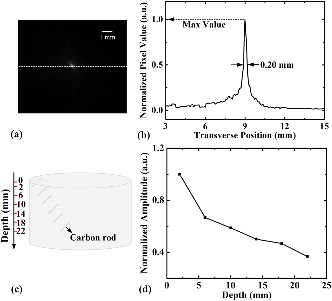
Fig. 2. (a) Typical cross-sectional PA image of a black human hair. (b) Quantitative analysis of the imaged size of the human hair. (c) The schematic of the phantom. (d) Normalized amplitude of the PA signal of the absorber at different depths.
Fig. 3. Performance of the excitation source and FT. (a) The dependence of the attenuation of the optical fiber on wavelength. (b) The intensity distribution of 64 outputs of the OFB. (c) Curve A, time-domain signal of the FT with a 10 MHz mechanical resonant frequency stimulated by 720 nm pulse laser; curve B, corresponding frequency spectrum to A. (d) Sensitivity of each element.
Fig. 4. (a) Two cross-sectional PA images and selected imaging positions of DIP joints in a female index finger. PH, phalanx; TE, tendon; AR, artery. (b) Comparison between the PA image and the corresponding MRI image.
Fig. 5. (a) Photograph of the location of the selected imaging area in a female left wrist. (b) Cross-sectional PA images of wrist joint. TE, tendon; AR, artery. (c) The corresponding MRI images.

Set citation alerts for the article
Please enter your email address
© Copyright 2018-2021 | Chinese Laser Press. All Rights Reserved 沪ICP备15018463号-20