• Infrared and Laser Engineering
  • Vol. 49, Issue 3, 0303010 (2020)
Yanjun Fu1, Yonghua Han1, Yuan Chen1, Pengfei Zhang1, Jiannan Gui1, Kequn Zhong1, and Caimin Huang2
Author Affiliations
  • 1Key Laboratory of Nondestructive Testing, Education Ministry of China, Nanchang Hangkong University, Nanchang 330063, China
  • 2Dongguan Jiyang Automation Technology co. LTD, Dongguan 523000, China
  • show less
    DOI: 10.3788/IRLA202049.0303010 Cite this Article
    Yanjun Fu, Yonghua Han, Yuan Chen, Pengfei Zhang, Jiannan Gui, Kequn Zhong, Caimin Huang. Research progress of 3D measurement technology based on phase coding[J]. Infrared and Laser Engineering, 2020, 49(3): 0303010 Copy Citation Text show less
    Measurement system diagram
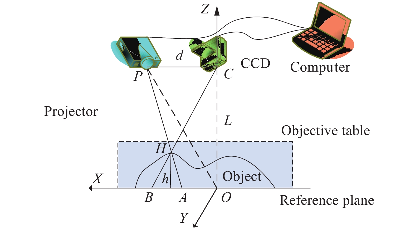
    Fig. 1. Measurement system diagram
    Phase code unwrapping flowchart
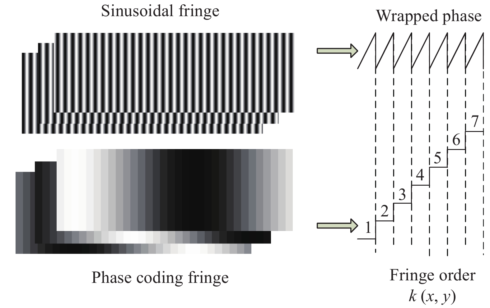
    Fig. 2. Phase code unwrapping flowchart
    Two-step coded phase and wrapped phase of a row
    Fig. 3. Two-step coded phase and wrapped phase of a row
    (a) Wrapped phase and the coded phase of a row; (b) Segmented fringe orderkof a row(a) 某一行的包裹相位和编码相位; (b) 某一行的分段条纹级次
    Fig. 4. (a) Wrapped phase and the coded phase of a row; (b) Segmented fringe orderkof a row (a) 某一行的包裹相位和编码相位; (b) 某一行的分段条纹级次
    Schematic diagram of a segmented fringe order connecting a row
    Fig. 5. Schematic diagram of a segmented fringe order connecting a row
    Minimum phase acquisition step phase map
    Fig. 6. Minimum phase acquisition step phase map
    Improved two-step phase coding schematic
    Fig. 7. Improved two-step phase coding schematic
    Quantized phase coding method
    Fig. 8. Quantized phase coding method
    Fringe order calculation process
    Fig. 9. Fringe order calculation process
    Initial quantization encoding phase of a row
    Fig. 10. Initial quantization encoding phase of a row
    Segment quantization phase decoding principle. (a) Segmented fringe order and reverse segmented fringe order; (b) Recovered absolute phase
    Fig. 11. Segment quantization phase decoding principle. (a) Segmented fringe order and reverse segmented fringe order; (b) Recovered absolute phase
    Generated fringe order graph
    Fig. 12. Generated fringe order graph
    Measured step phase and improved step phase of a row
    Fig. 13. Measured step phase and improved step phase of a row
    Schematic diagram of the implementation process of cycle correction method
    Fig. 14. Schematic diagram of the implementation process of cycle correction method
    Schematic diagram of n=2 phase shift coding method. (a) Phase-shifting fringe order; (b)Wrapped phase and fringe order of a row
    Fig. 15. Schematic diagram of n=2 phase shift coding method. (a) Phase-shifting fringe order; (b)Wrapped phase and fringe order of a row
    (a) Wrapping phase of a row; (b) Step phase of a row
    Fig. 16. (a) Wrapping phase of a row; (b) Step phase of a row
    Three - dimensional measurement result of the blade
    Fig. 17. Three - dimensional measurement result of the blade
    Result diagram of an isolated object
    Fig. 18. Result diagram of an isolated object
    Measurement results of the statue
    Fig. 19. Measurement results of the statue
    Measurement results of isolated objects
    Fig. 20. Measurement results of isolated objects
    Three-dimensional measurement of complex objects
    Fig. 21. Three-dimensional measurement of complex objects
    Three - dimensional measurement result of the mask
    Fig. 22. Three - dimensional measurement result of the mask
    Yanjun Fu, Yonghua Han, Yuan Chen, Pengfei Zhang, Jiannan Gui, Kequn Zhong, Caimin Huang. Research progress of 3D measurement technology based on phase coding[J]. Infrared and Laser Engineering, 2020, 49(3): 0303010
    Download Citation