
Jun Wu, Yuheng Zhu, Haoshuang Wang, Runxia Guo, Xiaoyu Zhang. Reconstruction of Pressure Distribution in High-Velocity Airflow Fields by Schlieren Decoupling of Velocity and Density Fields[J]. Acta Optica Sinica, 2023, 43(11): 1112004
- Acta Optica Sinica
- Vol. 43, Issue 11, 1112004 (2023)
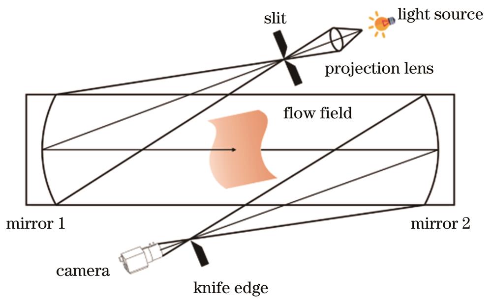
Fig. 1. Schematic diagram of Z-type optical part
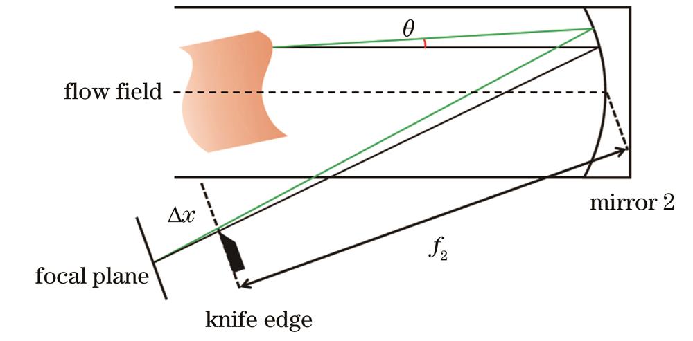
Fig. 2. Geometric relationship between deflection angle and offset
Fig. 3. Schematic diagrams of relative knife edge displacement of focal plane light source image. (a) Displacement of the light source image relative to the knife edge; (b) displacement of the knife edge relative to the light source image
Fig. 4. Schematic diagram of relative knife edge displacement of focal plane light source image
Fig. 5. The case of light passing through an axisymmetric temperature field
Fig. 6. Schematic diagram of central difference
Fig. 7. Real picture of the experimental system for measuring jet flow field
Fig. 8. Calibration images of knife edge
Fig. 9. Calibration curve of knife edge
Fig. 10. Schlieren image of the area to be measured without a flow field
Fig. 11. Two consecutive frames of schlieren images of micro turbojet tail jet field
Fig. 12. Density distribution of tail jet flow field of micro turbojet engine
Fig. 13. Velocity distribution of tail jet field of micro turbojet engine
Fig. 14. Velocity distribution of tail jet field of micro turbojet engine
Fig. 15. Pressure distribution in tail jet field of micro turbojet engine
Fig. 16. Dynamic pressure distribution of tail jet field of micro turbojet engine
Fig. 17. Dynamic pressure distribution of tail jet field of micro turbojet engine
Fig. 18. Pressure measurement of tail jet field of micro turbojet engine
Fig. 19. Comparison of two pressure measurements
|
Table 1. Speed measurement value and reconstruction value

Set citation alerts for the article
Please enter your email address
© Copyright 2018-2021 | Chinese Laser Press. All Rights Reserved 沪ICP备15018463号-20