• Chinese Optics Letters
  • Vol. 16, Issue 3, 031701 (2018)
Yi Wang1, Liang Feng1, Lida Zhu2, Hongxian Zhou1, and Zhenhe Ma1、*
Author Affiliations
  • 1School of Control Engineering, Northeastern University at Qinhuangdao, Qinhuangdao 066004, China
  • 2School of Electrical Engineering, Yanshan University, Qinhuangdao 066004, China
  • show less
    DOI: 10.3788/COL201816.031701 Cite this Article Set citation alerts
    Yi Wang, Liang Feng, Lida Zhu, Hongxian Zhou, Zhenhe Ma. Measurement of ocular axial length using full-range spectral-domain low-coherence interferometry[J]. Chinese Optics Letters, 2018, 16(3): 031701 Copy Citation Text show less
    Schematic of recognition of (a) positive and (b) negative depths.
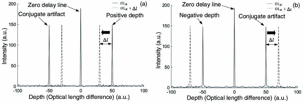
    Fig. 1. Schematic of recognition of (a) positive and (b) negative depths.
    (a) Schematic of the experimental setup. (b)–(d) Schematics of the rotating disk: (b) No reference and probe beams travel through the disk; (c) probe beam PB1 and reference beam RB1 travel through windows W3 and W11, respectively; (d) probe beam PB1 and reference beam RB1 pass through windows W3 and W12, respectively. SLD, super-luminescent diode; FC, fiber coupler; C, collimator; NPBS, non-polarizing beam splitter; L, lens; M, mirror; RD, rotating disk; TG, transmission grating; SM, servo motor; FT, fixation target; DM, dichroic mirror; PB, probing beam; RB, reference beam; W, optical window.
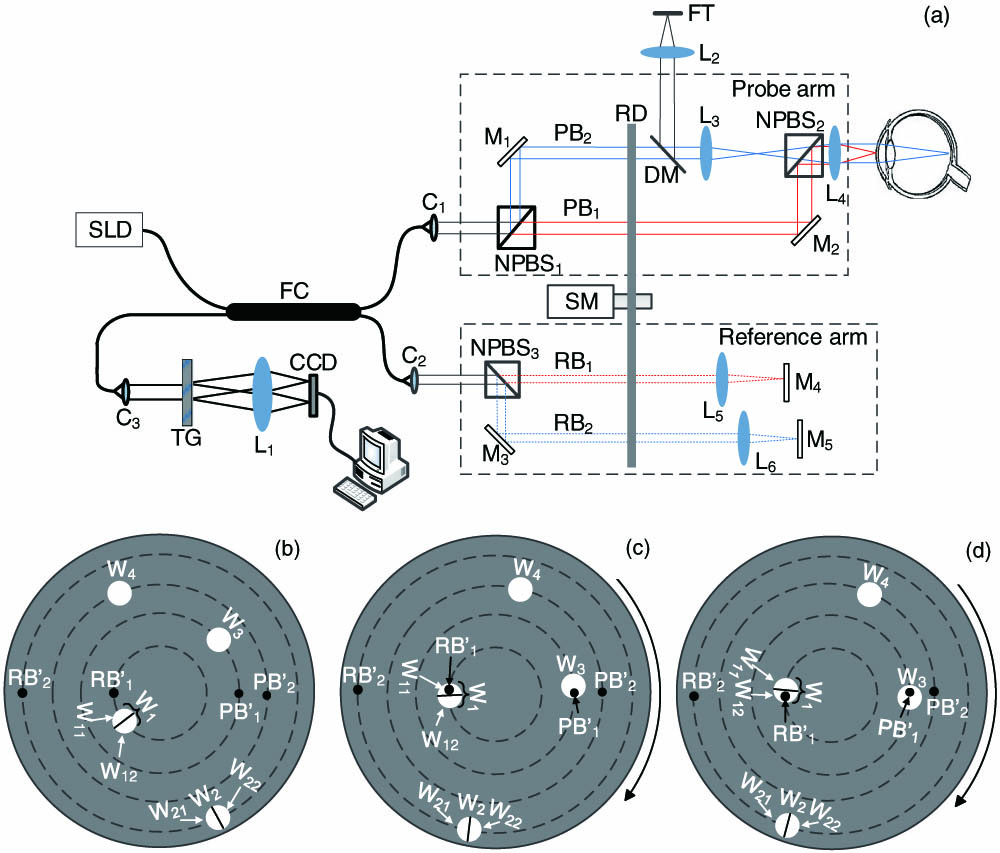
    Fig. 2. (a) Schematic of the experimental setup. (b)–(d) Schematics of the rotating disk: (b) No reference and probe beams travel through the disk; (c) probe beam PB1 and reference beam RB1 travel through windows W3 and W11, respectively; (d) probe beam PB1 and reference beam RB1 pass through windows W3 and W12, respectively. SLD, super-luminescent diode; FC, fiber coupler; C, collimator; NPBS, non-polarizing beam splitter; L, lens; M, mirror; RD, rotating disk; TG, transmission grating; SM, servo motor; FT, fixation target; DM, dichroic mirror; PB, probing beam; RB, reference beam; W, optical window.
    Distinguishing between positive and negative depths. The glass slide is located in (a) positive and (b) negative depth ranges. (c) The zero delay line is positioned between the two surfaces of the glass slide.
    Fig. 3. Distinguishing between positive and negative depths. The glass slide is located in (a) positive and (b) negative depth ranges. (c) The zero delay line is positioned between the two surfaces of the glass slide.
    Representative results of (a) cornea and (b) retina.
    Fig. 4. Representative results of (a) cornea and (b) retina.
     Right EyeLeft Eye
     Presented SystemIOL MasterPresented SystemIOL Master
    VolunteerCTALALCTALAL
    10.4723.6423.190.4724.6624.67
    20.5225.1525.240.5224.9424.50
    30.5325.8826.040.5425.5825.38
    40.5025.1524.800.5024.8524.90
    50.5524.8924.870.5524.8324.62
    Table 1. Experimental Results with the Presented System and with IOL Master 500 (mm)a
    Yi Wang, Liang Feng, Lida Zhu, Hongxian Zhou, Zhenhe Ma. Measurement of ocular axial length using full-range spectral-domain low-coherence interferometry[J]. Chinese Optics Letters, 2018, 16(3): 031701
    Download Citation