• Photonics Research
  • Vol. 9, Issue 6, 1003 (2021)
Cheng Shen1、*, Mingshu Liang1, An Pan2, and Changhuei Yang1
Author Affiliations
  • 1Department of Electrical Engineering, California Institute of Technology, Pasadena, California 91125, USA
  • 2Xi’an Institute of Optics and Precision Mechanics (XIOPM), Chinese Academy of Sciences (CAS), Xi’an 710119, China
  • show less
    DOI: 10.1364/PRJ.419886 Cite this Article Set citation alerts
    Cheng Shen, Mingshu Liang, An Pan, Changhuei Yang. Non-iterative complex wave-field reconstruction based on Kramers–Kronig relations[J]. Photonics Research, 2021, 9(6): 1003 Copy Citation Text show less
    Principle of KKSAI. (a) Schematic of experimental setup, where pupil modulation is achieved by an SLM-based module. (b) Simplified 4f system corresponding to (a). (c) Simulated complex-valued sample. (d) Amplitude pupil modulation indicated by the green circle, whose center is (ui,vi). (e) Measured images corresponding to (d). (f) KKSAI reconstruction algorithm flowchart. It finally recovers the pupil-limited sample spectrum. MMF, multimode fiber; CL, collimating lens; RL, relay lens; P, polarizer; BS, beam splitter; SLM, spatial light modulator; TL, tube lens.
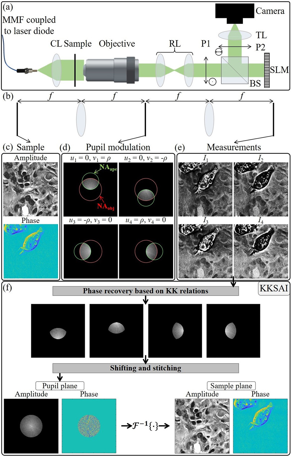
    Fig. 1. Principle of KKSAI. (a) Schematic of experimental setup, where pupil modulation is achieved by an SLM-based module. (b) Simplified 4f system corresponding to (a). (c) Simulated complex-valued sample. (d) Amplitude pupil modulation indicated by the green circle, whose center is (ui,vi). (e) Measured images corresponding to (d). (f) KKSAI reconstruction algorithm flowchart. It finally recovers the pupil-limited sample spectrum. MMF, multimode fiber; CL, collimating lens; RL, relay lens; P, polarizer; BS, beam splitter; SLM, spatial light modulator; TL, tube lens.
    Analogy between KKSAI measurement and off-axis hologram. (a) Measurement I1 between its corresponding complex-valued spectrum subregion and the amplitude of its FT. (b) Shifted spectrum subregion still brings in the same measurement due to the frequency shifting property of FT and phase loss of the square-law detector. (c) The shifted spectrum subregion can be hypothetically decomposed into a Dirac delta function and the shifted scattered complex-valued function.
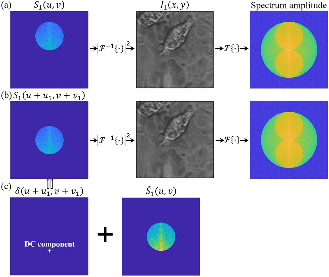
    Fig. 2. Analogy between KKSAI measurement and off-axis hologram. (a) Measurement I1 between its corresponding complex-valued spectrum subregion and the amplitude of its FT. (b) Shifted spectrum subregion still brings in the same measurement due to the frequency shifting property of FT and phase loss of the square-law detector. (c) The shifted spectrum subregion can be hypothetically decomposed into a Dirac delta function and the shifted scattered complex-valued function.
    Titchmarsh theorem applied to a band-limited signal. (a) Amplitude and (b) phase of s˜(l→) with bandwidth of ρNAape. (c) Logarithm of its 2D Fourier amplitude spectrum. (d) Logarithm of its 1D Fourier amplitude spectrum along the l∥ axis and its shifted copies by (e) |ρ→r|<ρNAape and (f) |ρ→r|=ρNAape.
    Fig. 3. Titchmarsh theorem applied to a band-limited signal. (a) Amplitude and (b) phase of s˜(l) with bandwidth of ρNAape. (c) Logarithm of its 2D Fourier amplitude spectrum. (d) Logarithm of its 1D Fourier amplitude spectrum along the l axis and its shifted copies by (e) |ρr|<ρNAape and (f) |ρr|=ρNAape.
    Scanning scheme examples to cover the entire pupil. (a) Four circular apertures; (b) two rectangular apertures. The circled numbers are used to label the measurement sequence.
    Fig. 4. Scanning scheme examples to cover the entire pupil. (a) Four circular apertures; (b) two rectangular apertures. The circled numbers are used to label the measurement sequence.
    Reconstruction of phase-only samples by two existing methods and our proposed method. (a) Weak phase sample; (b) strong phase sample.
    Fig. 5. Reconstruction of phase-only samples by two existing methods and our proposed method. (a) Weak phase sample; (b) strong phase sample.
    Reconstruction of complex-valued sample by two existing methods and our proposed method. (a) Phase; (b) amplitude.
    Fig. 6. Reconstruction of complex-valued sample by two existing methods and our proposed method. (a) Phase; (b) amplitude.
    Effect of distance between aperture edge and pupil center on the final reconstruction accuracy.
    Fig. 7. Effect of distance between aperture edge and pupil center on the final reconstruction accuracy.
    KKSAI based on the scanning scheme with only two measurements. (a) Measurements; (b) reconstruction.
    Fig. 8. KKSAI based on the scanning scheme with only two measurements. (a) Measurements; (b) reconstruction.
    Experimental results for a microlens array. (a) Reconstructions of a single microlens by PM-DPC, PM-FPM, and KKSAI using four measurements. (b) A close-up view of the SEM image of the microlens array (adapted from Thorlabs website). (c) Radial average profile of three phase recoveries compared with the ground truth (GT).
    Fig. 9. Experimental results for a microlens array. (a) Reconstructions of a single microlens by PM-DPC, PM-FPM, and KKSAI using four measurements. (b) A close-up view of the SEM image of the microlens array (adapted from Thorlabs website). (c) Radial average profile of three phase recoveries compared with the ground truth (GT).
    Experimental results for a thyroid carcinoma pap smear slide. (a) Two out of four measurements acquired by KKSAI and their Fourier amplitude spectrum. (b) Amplitude reconstruction by PM-FPM and KKSAI compared with ground truth. (c) Phase reconstruction by PM-DPC, PM-FPM, and KKSAI compared with ground truth.
    Fig. 10. Experimental results for a thyroid carcinoma pap smear slide. (a) Two out of four measurements acquired by KKSAI and their Fourier amplitude spectrum. (b) Amplitude reconstruction by PM-FPM and KKSAI compared with ground truth. (c) Phase reconstruction by PM-DPC, PM-FPM, and KKSAI compared with ground truth.
    Chromatic aberration correction by digital refocusing ability of KKSAI. (a) Reconstructed amplitudes by KKSAI of three channels. (b) Reconstructed phases by KKSAI of three channels. (c) Digitally refocused amplitudes with the corresponding refocusing distance labeled at the bottom. (d) Color composite of three channels before and after digital refocusing with the enlargements showing improved image quality. R, red (638 nm); G, green (532 nm); B, blue (405 nm).
    Fig. 11. Chromatic aberration correction by digital refocusing ability of KKSAI. (a) Reconstructed amplitudes by KKSAI of three channels. (b) Reconstructed phases by KKSAI of three channels. (c) Digitally refocused amplitudes with the corresponding refocusing distance labeled at the bottom. (d) Color composite of three channels before and after digital refocusing with the enlargements showing improved image quality. R, red (638 nm); G, green (532 nm); B, blue (405 nm).
    Complex wave-field reconstruction by KKSAI based on only two measurements. (a) Scanning scheme, raw measurements, and their spectrum amplitude; (b) and (c) reconstructed amplitude and phase, respectively, by KKSAI from two measurements, four measurements, and PM-FPM with 47 measurements. Here PM-FPM reconstruction is taken as the reference to calculate the FSIM metric for KKSAI reconstruction.
    Fig. 12. Complex wave-field reconstruction by KKSAI based on only two measurements. (a) Scanning scheme, raw measurements, and their spectrum amplitude; (b) and (c) reconstructed amplitude and phase, respectively, by KKSAI from two measurements, four measurements, and PM-FPM with 47 measurements. Here PM-FPM reconstruction is taken as the reference to calculate the FSIM metric for KKSAI reconstruction.
    MetricPM-DPCPM-FPMKKSAI
    (a)MSE4.80×1094.53×1097.84×1010
    FSIM0.99991.00000.9998
    Time (s)2.0128.432.12
    (b)MSE0.17110.06400.0136
    FSIM0.98941.00000.9973
    Time (s)1.6777.332.03
    Table 1. Quantitative Evaluation of Reconstructions in Fig. 5
    MetricPM-DPCPM-FPMKKSAI
    PhaseMSE0.05310.01200.0037
    FSIM0.99340.99970.9976
    AmplitudeMSE/1.55×1083.78×104
    FSIM/1.00000.9965
    Time (s)3.83109.372.82
    Table 2. Quantitative Evaluation of Reconstructions in Fig. 6
    Overlapping Region
    Phase0.99400.99670.99900.9926
    Amplitude0.99970.99980.99990.9998
    Table 3. Similarity Evaluation of Overlapping Spectrum Regions in Fig. 6
    Overlapping Region
    Phase0.98720.99270.98640.9691
    Amplitude0.99910.99980.99860.9991
    Table 4. Similarity Evaluation of Overlapping Spectrum Regions in Fig. 10
    Cheng Shen, Mingshu Liang, An Pan, Changhuei Yang. Non-iterative complex wave-field reconstruction based on Kramers–Kronig relations[J]. Photonics Research, 2021, 9(6): 1003
    Download Citation