• Photonics Research
  • Vol. 10, Issue 8, 1828 (2022)
Chen Zhao1、2, Guangwei Hu2, Yang Chen2, Qing Zhang2, Yongzhe Zhang1、3、*, and Cheng-Wei Qiu2、4、*
Author Affiliations
  • 1Faculty of Materials and Manufacturing, Beijing University of Technology, Beijing 100124, China
  • 2Department of Electrical and Computer Engineering, National University of Singapore, Singapore 117583, Singapore
  • 3e-mail: yzzhang@bjut.edu.cn
  • 4e-mail: chengwei.qiu@nus.edu.sg
  • show less
    DOI: 10.1364/PRJ.459383 Cite this Article Set citation alerts
    Chen Zhao, Guangwei Hu, Yang Chen, Qing Zhang, Yongzhe Zhang, Cheng-Wei Qiu. Unidirectional bound states in the continuum in Weyl semimetal nanostructures[J]. Photonics Research, 2022, 10(8): 1828 Copy Citation Text show less

    Abstract

    Recently studied bound states in the continuum (BICs) enable perfect localization of light and enhance light–matter interactions although systems are optically open. They have found applications in numerous areas, including optical nonlinearity, light emitters, and nano-sensors. However, their unidirectional nature in nonreciprocal devices is still elusive because such trapping states are easily destroyed when the symmetry of an optical system is broken. Herein, we propose nonreciprocal and dynamically tunable BICs for unidirectional confinement of light and symmetry-protected BICs at Γ-point by introducing antiparallel magnetism into the optical system. We demonstrate that such BICs can be achieved by using topological magnetic Weyl semimetals near zero-index frequency without any structural asymmetry, and are largely tunable via modifying the Fermi level. Our results reveal a regime of extreme light manipulation and interaction with emerging quantum materials for various practical applications.

    1. INTRODUCTION

    Bound states in the continuum (BICs), as perfect confinement of light in an open system, have been extensively studied both experimentally and theoretically [13], spanning from quantum mechanics to photonics [4,5]. Such non-radiating eigenmodes are peculiar states that remain localized with lifetimes that diverge to infinity, although a leaky channel may be present. Various types of BICs that originate from diverse physical mechanisms have been proposed in numerous geometrical photonics systems, such as symmetry-protected BICs, Friedrich–Wintgen (FW) BICs, and accidental single-resonance BICs [6]. These BICs facilitate exciting applications including enhanced optical nonlinearity [7], high-efficiency light guiding, and optical sensing [8] and have been implemented in zero-index plasmonic metamaterials [9,10], photonic slabs [11], high-index Mie resonators [12], and others [13]; they usually have a topological nature [14] and significantly enhanced light–matter interactions [1517]. However, current investigations on BICs are restricted in reciprocal systems, and their mechanisms and behaviors in nonreciprocal systems are still elusive, as well as their applications to nonreciprocal devices. Nonreciprocal devices that exhibit different responses of the same transmission channel when their sources and detectors are interchanged have become fundamental building blocks in photonic systems [1820], and drive widespread applications with asymmetric wave manipulation [21] assisted by magnetic bias, nonlinearities, or external gains and losses [22,23]. Such applications usually require nonreciprocal eigenmodes with high quality factors (Q-factors) and large contrast ratios simultaneously [24], especially in the field of unidirectional or angle-selective sensing and emission [25]. Therefore, nonreciprocal BICs appear to be significantly important and need to be more explored.

    However, nonreciprocal BICs are very challenging to realize in generic systems. One reason is that the system supporting stable BICs is invariant under C2yT (rotation of π about the y axis followed by time reversal) and σy (up–down mirror symmetry of the xz plane) operators (corresponding to the coordinates in Fig. 1) to achieve zero radiation loss [26]. Generally, the nonreciprocal system is more convenient to achieve by introducing an external magnetic field compared to some metamaterials with complex structural design, and time-reversal symmetry is broken in these magnetic systems, which means T(ε¯¯)ε¯¯, where ε¯¯ is the permittivity tensor of materials. So such BICs can hardly be supported. The other is that spectral nonreciprocity is imperative for unidirectional BICs, which have to break inversion symmetry of the band structure in k space, i.e., ω(k)ω(k). Such implementation needs to break the rotation-time-reversal symmetry (rotation of π about the x axis followed by time reversal) [27,28], but usually degrades BICs and inevitably reduces their Q-factors due to the destruction of geometric symmetry. Consequently, the light emission efficiency and isolation contrast in the system are relatively low, which limits its application in photonic circuits [29,30]. For asymmetric light manipulation operating at different frequencies, schemes in tuning unidirectional BICs are indispensable in designing the optical system. Although some literatures have reported dynamic BICs via photodoping or electric bias [31,32], the significant material losses and imperfection of the structure, such as increased roughness or resultant deformation, largely limit the achievement of tunable BICs. Hence, dynamically tunable BICs [33] with a distinguished response such as nonreciprocity remain largely unexplored.

    (a) Geometry of the plasmonic coating sanwiched structure. (b) Antiparallel-magnetism configuration with MWS coating. Unidirectional quasi-BICs and their corresponding radiation leakage in left (blue) and right (red) propagation are presented. BICs are achieved in both propagation directions in (a), while only the right propagating BIC (red) is in (b). (c) Angular-frequency dispersions of MWS in different amounts of magnetization. Red, yellow, green, blue, and purple lines correspond to different εa when 2b equals q, 3q, 5q, 10q, and 16q, respectively, where q=1×10⁸ m−1. The inset is the dependence of εa on 2b at ENZ frequency (vertical dotted line). (d) Angular-frequency dispersions of permittivity and effective permittivity in narrow frequency range.

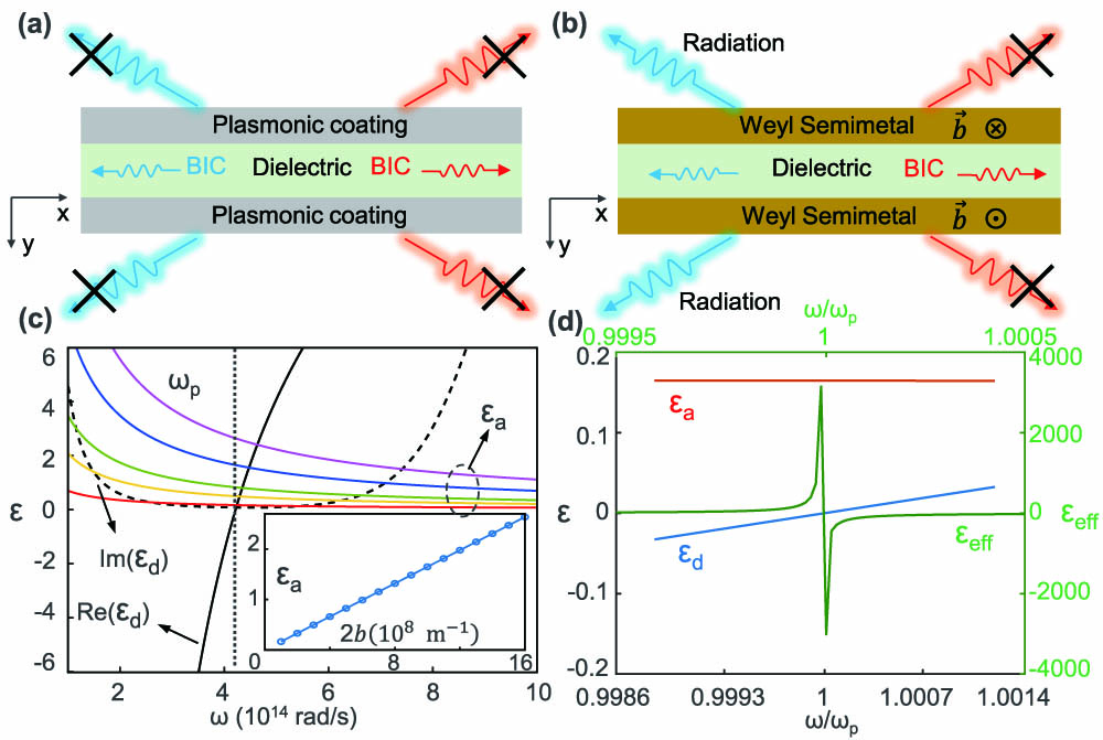
    Figure 1.(a) Geometry of the plasmonic coating sanwiched structure. (b) Antiparallel-magnetism configuration with MWS coating. Unidirectional quasi-BICs and their corresponding radiation leakage in left (blue) and right (red) propagation are presented. BICs are achieved in both propagation directions in (a), while only the right propagating BIC (red) is in (b). (c) Angular-frequency dispersions of MWS in different amounts of magnetization. Red, yellow, green, blue, and purple lines correspond to different εa when 2b equals q, 3q, 5q, 10q, and 16q, respectively, where q=1×10⁸  m1. The inset is the dependence of εa on 2b at ENZ frequency (vertical dotted line). (d) Angular-frequency dispersions of permittivity and effective permittivity in narrow frequency range.

    In this paper, we propose a feasible paradigm toward unidirectional and dynamic BICs by introducing magnetism asymmetry from magnetic Weyl semimetal (MWS) slabs as shown in Fig. 1(b). By incorporating novel MWS into the system, large nonreciprocity but lower losses can be achieved without external magnetic bias, compared to the conventional counterpart of magnetoplasmonic materials [34,35]. The major findings of this work are that properly pairing MWS in an antiparallel-magnetism configuration could establish unidirectional quasi-BICs and a symmetry-protected quasi-BIC at Γ-point without breaking either C2yT or σy symmetry, and dynamically tunable quasi-BICs are attainable through chemical doping. Our results promise the extreme manipulation of light in emerging quantum and low-dimensional nanomaterials [3638], taking advantage of superior properties in MWS.

    2. OPTICAL RESPONSE OF MAGNETIC WEYL SEMIMETAL

    As a class of emerging low-dimensional quantum materials, MWS simultaneously supports intrinsic optical nonreciprocity and magneto-optic (MO) plasmonics characteristics [39,40]. The large MO response is endowed by its unique topological electronic bands and is easily tunable by the chemical doping and its intrinsic momentum. With net zero chirality, pairs of topologically protected gapless crossing points, known as Weyl nodes, exist at the corners of the Brillouin zone in conical reciprocal space, resulting in monopoles and anti-monopoles with different Berry curvatures [41,42]. These paired Weyl nodes exhibit opposite chirality and are separated by a wave vector b in the first Brillouin zone or by an energy offset b0 in the energy spectrum. Direct observations of Weyl nodes, Fermi arcs, and their relation are necessary to confirm the existence of an MSW state. Recently, comprehensive evidence on the MWS state in Co3Sn2S2 was reported [42], verifying that its Fermi-arc connectivity varies with surface termination. Following this work, more experimetal realizations of MWS and its physical properties and effects associated with Weyl nodes were pursued [43,44]. Stimulated by the extensive demand on the application of MWS in nanophotonics, its optical model and electrodynamic response have been explored in previous works [4548].

    A concrete expression of its optical response can be described by the additional axion term in the electromagnetic action and has been applied in studying magnetic surface plasmon polaritons [45,46] and nonreciprocal modes in waveguides [47]. The constitutive relation of MWS can be written as [45] D=εdE+ie2πω2b×Eie2πωc2b0B.

    Here, εd denotes the major permittivity function of the Dirac semimetal. The first term denotes the major dielectric response, the second represents the anomalous Hall effect, manifesting itself as an MO effect, and the third describes the chiral magnetic effect, stimulated by an applied magnetic field. Without considering external magnetic bias on MWS in an equilibrium state, the third term can be neglected. Such schemes are experimentally realized in EuCd2As2 [46,48]. Further, we assume an unperturbed magnetic permeability (i.e., μ=1), and crystal orientation is chosen such that b is along z direction, i.e., b=bz. Thus, the permittivity tensor of MWS can be written as ε¯¯=(εdiεa0iεaεd000εd),where the off-diagonal component is εa=2be24π2ωε0 [49].

    Moreover, applying the random phase approximation and considering the interband electronic transitions in the Dirac cone, the diagonal term is derived through Kubo formalism as the following form [47]: εd=εb2rsg3πΩ2+rsg6π[ln(4Λ2|Ω24|)+iπG(Ω2)],where εb is the background permittivity accounting for contributions from all bands below the Dirac cone, G(E)=n(E)n(E), with n(E) being the Fermi distribution function [46], and Ω=(ω+iτ)/EF is the normalized complex frequency, with EF being the Fermi level and τ1 being the Drude damping rate. Also, g is the number of Weyl points, which is two in our case; rs=e2/4πε0vF and Λ=Ec/EF, where Ec is the cutoff energy. Importantly, such an MO response is fundamentally different from the well-known magnetized plasma under external magnetic biases, although both share similar forms of permittivity tensors in Eq. (2). The MWS obtains a magnetic effect from the pseudo-vector 2b without an external magnetic field, playing the role of an effective magnetic field. Such an intrinsic MO response is solely due to the electronic structure of MWS. Following Ref. [50], we use parameters εb=6.2, Λ=3, and EF=0.3  eV. We observe an obvious magneto-plasmonic response with the robust and low-loss epsilon near zero (ENZ) point near the plasma frequency, as shown in Fig. 1(c). The solid and dashed black lines are, respectively, the real and imaginary parts of εd, while the colored solid lines represent εa in different 2b. The enlarged plot of permittivity dispersion around the plasma frequency when 2b=1×10⁸  m1 is shown in Fig. 1(d). The permittivity components and associated nonreciprocal response can be manipulated through changing EF, which is very important for dynamically tunable BICs as shown later. Though the imaginary part of epsillon is unavoidable at this ENZ point, destorying BIC, the Q-factor around this point is still relatively high, thus forming a quasi-BIC, which possesses a high contrast ratio and can be applied in photonics devices as well.

    3. GENERATION OF UNIDIRECTIONAL QUASI-BIC AND SYMMETRY-PROTECTED QUASI-BIC IN NONRECIPROCAL SYSTEM

    Having established the optical responses of MWS, we discuss more details of unidirectional quasi-BICs in our structure composed of a planar dielectric slab covered by MWS, where the direction of magnetism is perpendicular to the incidence plane (Voigt configuration). A leaky mode could exist inside this dielectric core with the complex propagation constant β, and the disappearance of radiation shows a feature of quasi-BICs when the dielectric core is covered by plasmonic materials [Fig. 1(a)] [9]. However, unidirectional quasi-BICs appear in the antiparallel-magnetism case, which means the directions of 2b in upper and lower MWS layers are antiparallel to each other [Fig. 1(b)], where the radiation leakage along positive-x direction is perfectly forbidden, while that along the negative direction is open. Considering our Voigt configuration under transverse-magnetically polarized oblique incidence with an angle of θ, no polarization conversion is allowed. The dispersion relation in MWS layer is kx2+kym2=k02εeff, where kym is the y component of the wave vector in MWS. εeff=εd2εa2εd denotes effective permittivity. When εd is close to zero without considering intrinsic loss, εeff tends to become infinite while εa remains almost unchanged, leading to a singular point in the reflection spectrum. Figures 2(a) and 2(b) show the reflection spectrum in parallel- and antiparallel-magnetism cases, where the vanishing feature of resonances suggests the existence of BICs. The off-Γ BIC arises from the coupling between extreme plasmonic resonance in the coating and Fabry–Perot resonance of the slab [9]. In our cases, considering the reflection at the interface between the MWS and dielectric, the condition of Fabry–Perot resonance is obtained as k0dcεcsin2θ+φr=nπ,where sinθ=kx/k0. εc and dc are permittivity and thickness of the dielectric slab. Here, φr is the extra phase introduced by reflection coefficients on two interfaces of the core layer because it contains the off-diagonal component in the permittivity tensor. In the parallel-magnetism case, eiφr=r+r, where r± represent reflection coefficients on lower (+) and upper sides (−) of the dielectric slab, respectively, and they are the function of effective wave vector k± in the MWS layer given by k±=kym±ikxεaεdεeff.

    Reflection spectra for structure with (a) parallel and (b) antiparallel magnetism when the thickness of MWS is 0.1 μm; εc=5 and dc=1 μm. Reflection spectra for structure with infinite thickness of MWS layers at two sides with (c) parallel and (d) antiparallel magnetism when εd=1 and εa=0.2. The white dashed line denotes ENZ frequency.

    Figure 2.Reflection spectra for structure with (a) parallel and (b) antiparallel magnetism when the thickness of MWS is 0.1 μm; εc=5 and dc=1  μm. Reflection spectra for structure with infinite thickness of MWS layers at two sides with (c) parallel and (d) antiparallel magnetism when εd=1 and εa=0.2. The white dashed line denotes ENZ frequency.

    Therefore, the Fabry–Perot resonance is symmetric regardless of propagation directions [Fig. 2(c)]. Such results are obtained from an ideal model in which a dielectric slab is covered by infinite MWS with εd=1, which contains a magnetic response outside the cavity. However, in the antiparallel-magnetism case, the extra phase becomes two different forms as eiφr+=r+r+ and eiφr=rr, where the sign represents forward (+kx) and backward (kx) propagation, respectively, resulting in asymmetric distribution of the reflection spectrum [Fig. 2(d)]. Such an extra phase influences the performance of unidirectional quasi-BICs because its eigenfrequency is not exactly at Fabry–Perot resonance but close to it. So the resonance cannot be perfectly coupled, thus forming the quasi-BIC, as further explicitly discussed in Appendix A. The white line in Fig. 2(d) represents the frequency when εd=0, defined as ENZ frequency, corresponding to plasma frequency. It intersects with Fabry–Perot resonance only in the +kx region, leading to a unidirectional quasi-BIC emerging in this case.

    To better illustrate the unidirectional quasi-BIC, we performed an eigenmode analysis in the antiparallel-magnetism case [Fig. 1(b)]. Complex dispersion can be found in the pole of the scattering matrix of the source-free Maxwell equations, which can be derived into the following form: Ψ(kx)Ψ(kx)eikycdcΦ(kx)Φ(kx)eikycdc=0,and the dispersion in the parallel-magnetism case is as follows: Ψ(kx)Ψ(kx)eikycdcΦ(kx)Φ(kx)eikycdc=0.

    Here, Ψ and Φ are the functions of kx, and kyc is the y component of the wave vector in the central dielectric layer. A concrete expression and detailed derivation can be found in Appendix B. With careful examination by comparing these two equations, one can easily prove that Eq. (6) does not follow spatial-inversion symmetry. In particular, several eigenmodes of interest are plotted in Fig. 3(a), which are responsible for the sharp resonant reflection features in Fig. 2(b), and they are asymmetrically distributed in +kx and kx regions. Three symmetric modes are labeled as forward mode I (blue), backward mode (green) in the +kx region, and forward mode II (red) in the kx region, and only β of forward mode I is non-zero at the ENZ frequency, which is possible to support quasi-BIC. Compared to Fig. 2(d), the Fabry–Perot resonance is determined by forward mode I and backward mode branches, which are in opposite slopes in the narrow bandwidth a little below the ENZ frequency. Forward mode II dramatically departs from its location in the parallel-magnetism case, remaining only in the high frequency branch, and the other half disappears. Moreover, the symmetry-protected quasi-BIC exists at Γ-point in the antiparallel-magnetism case, determined by antisymmetric modes (yellow) in two wave vector regions, while it vanishes in the parallel-magnetism case. The underlying physics is that the antiparallel-magnetism case preserves C2yT and σy symmetry because the magnetic field, being a pseudovector, gains an additional sign flip under mirror symmetry operation. As the time-reversal symmetry is broken in the system, the permittivity tensor of MWS shown in Eq. (2) under a rotation operator along the y axis becomes C2yε¯¯(x,y,z)=ε¯¯(x,y,z)*. Then, combining the T operation, we obtain C2yTε¯¯(x,y,z)=ε¯¯(x,y,z)*=ε¯¯(x,y,z).

    (a) Angular-frequency dispersions of normalized Re(β) for some eigenmodes related to the quasi-BIC. The antisymmetric mode has antisymmetric field distribution, shown in Appendix C. Angular-frequency dispersions of normalized Im(β) of (b) forward mode I and (c) other eigenmodes. (d) Radiative Q-factor of unidirectional quasi-BIC (blue) and symmetry-protected quasi-BIC (yellow), and radiation loss contrast between two modes in two opposite directions. (e) Time-snapshot of the magnetic field profile at the frequency close to ENZ frequency. (f) Time-snapshot of magnetic field intensity and electric field.

    Figure 3.(a) Angular-frequency dispersions of normalized Re(β) for some eigenmodes related to the quasi-BIC. The antisymmetric mode has antisymmetric field distribution, shown in Appendix C. Angular-frequency dispersions of normalized Im(β) of (b) forward mode I and (c) other eigenmodes. (d) Radiative Q-factor of unidirectional quasi-BIC (blue) and symmetry-protected quasi-BIC (yellow), and radiation loss contrast between two modes in two opposite directions. (e) Time-snapshot of the magnetic field profile at the frequency close to ENZ frequency. (f) Time-snapshot of magnetic field intensity and electric field.

    It is one of the sufficient conditions for symmetry-protected BICs [26] existing in nonreciprocal systems, and the detailed derivation can be found in Appendix E.

    Importantly, the imaginary part of an eigenmode, i.e., Im(β), vanishes for forward mode I [Fig. 3(b)], indicating the disappearance of energy leakage. The radiative Q-factor (see the definition in Ref. [51]) of this mode (blue) is plotted in Fig. 3(d), diverging near the ENZ frequency. Moreover, Im(β) of other eigenmodes are displayed in Fig. 3(c), where only antisymmetric eigenmodes converge to zero point. That supports the symmetry-protected quasi-BIC at Γ-point, while the other two modes are all leaky. The radiative Q-factors of symmetry-protected quasi-BICs (yellow) are lower than those of unidirectional quasi-BICs [Fig. 3(d)], and decay more rapidly, indicating that they are sensitive to tiny external perturbations. The unidirectional feature of unidirectional quasi-BIC can be obviously reflected from the radiation loss contrast (red), defined as Im(β+)Im(β), where β± represent the wave vector of eigenmodes in the +kx and kx regions, respectively. The maximum nonreciprocity is achieved at the ENZ frequency when quasi-BIC propagates in +kx direction without any radiation loss. The field distributions near this BIC are shown in Figs. 3(e) and 3(f), corresponding to the incident angle of sinθ=0.778. A resonant localized magnetic field in out-of-plane direction exists within the dielectric slab, consistent with the non-radiating nature of the mode, while the electric field is mainly directed along the orthogonal direction, marked by the white arrows. Actually, this strong oscillation of the electric field works as orthogonal electric dipoles to excite volume-plasmon resonance in MWS layers. Only such resonance coupling with Fabry–Perot resonance can achieve the accidental BICs in this transversely homogenous waveguide. Therefore, such a unidirectional quasi-BIC is an FW BIC, which is not limited by the symmetry restrictions mentioned above.

    4. TUNABILITY ON UNIDIRECTIONAL BIC

    We now discuss the dynamic unidirectional quasi-BICs via tailoring the tunability of MWS based on two avenues available, by the argument of breaking the reciprocal response. First, one could change its intrinsic magnetization value in two MWS layers to break the time-reversal symmetry to generate unidirectional quasi-BICs. As shown in Figs. 4(a)–4(c), we vary the magnitude of its intrinsic magnetism in the lower MWS layer while keeping the upper MWS layer unchanged. A pair of asymmetric quasi-BICs still occur with different wave vectors [Fig. 4(a)], quite as expected due to the parallel magnetism. However, only one quasi-BIC exists in the +kx region when the MO response of the lower MWS disappears [Fig. 4(b)] or becomes enlarged [Fig. 4(c)]. Moreover, such a unidirectional quasi-BIC in forward direction carries a larger momentum and moves to a larger kx direction in the antiparallel-magnetism case. With too large magnetization, no unidirectional quasi-BIC is found, as the Fabry–Perot resonance is not supported near the ENZ frequency [Fig. 4(d)]. Notably, the symmetry-protected BIC still exists in the antiparallel-magnetism case when C2yT and σy symmetry is preserved [Fig. 4(d)], while it turns into a quasi-symmetry-protected BIC when such symmetry is broken [Fig. 4(c)]. In general, via tailoring the distance between Weyl nodes in momentum space in MWS independently without altering εd, we could tune quasi-BICs of both forward and backward directions in a designer manner.

    (a)–(d) Reflection spectra with different intrinsic magnetization values in two MWS layers. The insets are the corresponding schematic models. (e) Angular-frequency dispersions of the bulk MWS in different EF. Solid and dashed lines correspond to Re(εd) and Im(εd), respectively. (f) Dependence of ωp on EF. (g), (h) Reflection spectra with and without losses for EF=0.36 eV and EF=0.4 eV, corresponding to ENZ frequency of ωp=4.961×10¹⁴ rad/s and ωp=6.892×10¹⁴ rad/s, marked by horizontal dashed lines. In this case, the model is the same as the antiparallel-magnetism configuration in Fig. 2(b) except for dc=0.75 μm, with magnetization value being 2b=q in upper layer and 2b=−q in lower layer.

    Figure 4.(a)–(d) Reflection spectra with different intrinsic magnetization values in two MWS layers. The insets are the corresponding schematic models. (e) Angular-frequency dispersions of the bulk MWS in different EF. Solid and dashed lines correspond to Re(εd) and Im(εd), respectively. (f) Dependence of ωp on EF. (g), (h) Reflection spectra with and without losses for EF=0.36  eV and EF=0.4  eV, corresponding to ENZ frequency of ωp=4.961×10¹⁴  rad/s and ωp=6.892×10¹⁴  rad/s, marked by horizontal dashed lines. In this case, the model is the same as the antiparallel-magnetism configuration in Fig. 2(b) except for dc=0.75  μm, with magnetization value being 2b=q in upper layer and 2b=q in lower layer.

    Second, via controlling the EF of MWS, the ENZ frequency could be tuned in a broad range, thus tuning the unidirectional quasi-BIC in our case. The permittivity εd with different EF is plotted in Fig. 4(e), and it shows the ENZ frequency appears to be approximately linearly blueshifted with smaller losses when increasing EF [Fig. 4(f)]. Such a characteristic makes our tunability on quasi-BICs come true. Since the loss is one major limitation in practical implementation in most systems [52], as a comparison, we calculate the reflection spectra with small intrinsic loss γ=Im(εd) [Figs. 4(i) and 4(j)], calculated by Eq. (3) and without loss [Figs. 4(g) and 4(h)], at EF=0.36  eV and EF=0.4  eV. Indeed, the asymmetric leaky modes change dramatically in both forward and backward directions with varying EF. The comparison between them shows that the unidirectional quasi-BIC carries larger momentum to satisfy the condition of Fabry–Perot resonance in the region when EF increases, while the symmetry-protected quasi-BIC still exists, unperturbed by varying the EF, protected by C2yT symmetry as demonstrated above. Therefore, by carefully tuning the EF and setup of the model, we can obtain the unidirectional quasi-BIC in any appropriate frequency with different radiation angles. If losses are considered, though quasi-BICs are degraded to some extent with the decay of leaky modes and the blurring of spectra contrast, the physical mechanism remains evident as unidirectional quasi-BICs can also be observed at the original location. The effect of intrinsic losses in MWS on BICs is discussed in detail in Appendix F.

    5. CONCLUSION

    In conclusion, we realize unidirectional and dynamically tunable quasi-BICs in paired MWS slabs via tailoring their intrinsic MO responses. They show the extremely different radiation of forward and backward leaky modes—one mode perfectly closed despite being within the radiation channel, and the other open, which can be tuned by changing the geometric pairing and the EF of MWS. We discuss the symmetry requirement of symmetry-protected BICs in a nonreciprocal system. Our strategies neither rely on the discretized asymmetric lattice [14,52] to break the spatial-inversion symmetry, nor require the external magnetic bias, showcasing a new avenue of extreme wave manipulation with emerging exotic quantum materials.

    Acknowledgment

    Acknowledgment. Y. Z. acknowledges NSFC, and C. Q. acknowledges the A*STAR Pharos Program.

    APPENDIX A: QUASI-BOUND STATES IN THE CONTINUUM

    In this appendix, we discuss the behavior of quasi-BICs in the system with magnetism without considering the loss of MWS. In Fig. 2(d), two BICs occur in an antiparallel-magnetism case. The central one is symmetry-protected BIC. The right one is a nonreciprocal accidental one, which is the result of coupling between the plasma resonance in the MWS layer and Fabry–Perot resonance in the slab. We plot the reflection and transmission spectrum dependence on incident angle at one frequency near the plasma frequency at ω=4.2167×10¹⁴  rad/s [Fig. 5(a)]. It is clear to see that these two BICs locate at sinθ=0 and sinθ=0.778, respectively, and no resonance emerges in the kx region. As we know, a perfect BIC is lossless in resonance with an infinitely high Q-factor and vanishing resonance width. But in practical applications, only a quasi-BIC can be achieved because loss or the asymmetry of a structure can destroy resonances. Here, due to the effect of intrinsic magnetism in MWS, the shape of Fano resonance is distorted, with another peak showing up near the plasma frequency, as shown in Fig. 5(b), which is the reflection and transmission spectrum dependence on ω at a certain incident angle sinθ=0.778. The blue and red solid lines correspond to the amplitude of reflection and transmission coefficients, respectively, in the linear coordinate of the left y axis, while the dashed lines correspond to their values in log scale. The transmission spectrum is an obvious Fano resonance profile, where the left dip is at the plasma frequency of MWS, and the right peak is at the resonant transmission frequency, corresponding to the maximum and minimum of the reflection spectrum, respectively.

    (a) Reflection and transmission spectrum dependence on transverse wave vector kx at frequency ω=4.2167×10¹⁴ rad/s. (b) Reflection and transmission spectrum dependence on the frequency of incident light ω at certain incident angle sin θ=0.778. Solid and dashed lines represent the spectrum in linear coordinates and log scale, respectively.

    Figure 5.(a) Reflection and transmission spectrum dependence on transverse wave vector kx at frequency ω=4.2167×10¹⁴  rad/s. (b) Reflection and transmission spectrum dependence on the frequency of incident light ω at certain incident angle sinθ=0.778. Solid and dashed lines represent the spectrum in linear coordinates and log scale, respectively.

    Geometry of MWS sandwiched structure with (a) parallel magnetism and (b) antiparallel magnetism in the coatings.

    Figure 6.Geometry of MWS sandwiched structure with (a) parallel magnetism and (b) antiparallel magnetism in the coatings.

    APPENDIX B: DERIVATION OF SCATTERING MATRIX AND SOLUTION OF EIGENMODE

    In this appendix, we present the detailed derivation of the scattering matrix and eigenequations in both parallel-magnetism [Fig. 6(a)] and antiparallel-magnetism [Fig. 6(b)] cases. The configuration is the same as the one in the main text: a dielectric slab with permittivity εc and thickness dc covered by MWS layers at two sides. TM polarized light impinges on the upper MWS layer with incident angle θ, and the transverse wave vector is kx=k0sinθ, where k0 is the wave vector in free space.

    Here, we assume time harmonic oscillations in the form ei(k·rωt), and incident light is p polarized. The permittivity tensor is the same as Eq. (2). In our structure with five planar layers (top and bottom are regarded as two layers of air), denoted in Fig. 6(b), the general dispersion relation in each layer can be written as kyi=k02εikx2 for the non-magnetic dielectric layer and kym=k02(εd2εα2εd)kx2 for the MWS layer, where i=1,3,5. k0=ω/c is the wave vector in free space, and kx is the same for all layers due to the continuity of the tangential wave vector.

    As we know, the traditional transfer matrix is the recursion of interface information and propagating factors, which can be written in the following form for a multilayer structure with n cells: (t0)=ψn=Mn1Tn1Tn2T2M1ψ1=j=2n1Mn1TjM1(1r)=(tm11tm12tm21tm22).

    Tj is the transfer matrix in j units, which connects the field on two sides of one cell. t and r are the total transmission and reflection coefficients of the structure, respectively, assuming the unit incident intensity. Mj relates field information at the interface between j and j+1. The transfer matrix can be simplified to ψ5=M51T4T3T2M1ψ1,Tj=MjPjMj1,where Pj is the propagation matrix in the j layer.

    In MWS layers, M2 and M4 are functions of effective wave vector k± as the continuity of the tangential field in the boundary condition, which brings in the magnetic related off-diagonal element εa. For the parallel-magnetism case, the tangential electric field and magnetic field are related in the same form in two MWS layers: ωε0Exm=k+Hz+m+kHzm,and they are related in the following form in dielectric layers: ωε0Exi=kyiεiHz+i+kyiεiHzi.Here, i=1,3,5. Hz±m represent the z components of the magnetic field in forward and backward directions, and k± are the effective wave vectors shown in Eq. (A2). Therefore, we can obtain T4=T2 without breaking spatial inversion symmetry. However, in the antiparallel-magnetism case, this relation collapses as a different field expression at the boundary in upper MWS and lower MWS, which arises from the reversal of its intrinsic magnetism [50]. We first investigate the transfer matrix in the parallel-magnetism case, and the results of the transfer matrix are as follows: tm11=Δ+eikymdm(Γ+eikycdcΘ1ΓeikycdcΘ2)Δ+eikymdm(Γ+eikycdcΘ1Γ++eikycdcΘ2)tm12=Δeikymdm(Γ+eikycdcΘ1Γ++eikycdcΘ2)Δ++eikymdm(Γ+eikycdcΘ1ΓeikycdcΘ2)tm21=Δ+eikymdm(Γ+eikycdcΩ1ΓeikycdcΩ2)Δ+eikymdm(Γ+eikycdcΩ1Γ++eikycdcΩ2),tm22=Δeikymdm(Γ+eikycdcΩ1Γ++eikycdcΩ2)Δ++eikymdm(Γ+eikycdcΩ1ΓeikycdcΩ2),where kym and kyc=k02εckx2 are the y components of wave vectors in the MWS and dielectric slab with thicknesses dm and dc, respectively. Θ and Ω contain the propagation factors in MWS, which are Θ1=Δ++ΓeikymdmΔΓ++eikymdm,Θ2=Δ++Γ+eikymdmΔΓ+eikymdm,Ω1=Δ+ΓeikymdmΔ+Γ++eikymdm,Ω2=Δ+Γ+eikymdmΔ+Γ+eikymdm.

    Δ and Γ relate to the coupling relations of the effective wave vectors at the interface of air/MWS and dielectric/MWS, which are described as follows: Δ+=kyaεa+k;Δ++=kyaεa+k+;Δ+=kyaεak+;Δ=kyaεak;Γ++=kycεc+k+;Γ+=kycεck+;Γ=kycεck;Γ+=kycεc+k,where kya is the y component in air, and k± are effective wave vectors, described in Eq. (A2). The relation between scattering and transfer matrices is displayed in the following form [53]: S=1tm22(|TM|tm12tm211),where |TM|=tm11tm22tm12tm21, which is the determinate of the total transfer matrix.

    We can obtain the concrete form of the scattering matrix and get the eigenmode of the structure from the pole of it, which is the eigenfunction Δ+Γ+eikymdmΔ+Γ+eikymdmΔ+ΓeikymdmΔ+Γ++eikymdme2ikycdcΔΓ+eikymdmΔ++Γ+ekymdmΔΓ++eikymdmΔ++Γeikymdm=0.

    We assume Ψ(kx)=ΔΓ++eikymdmΔ++Γeikymdm,Ψ(kx)=Δ+Γ+eikymdmΔ+Γ+eikymdm,Φ(kx)=ΔΓ+eikymdmΔ++Γ+eikymdm,Φ(kx)=Δ+ΓeikymdmΔ+Γ++eikymdm.

    Therefore, Eq. (B2) can be simplified to Ψ(kx)Ψ(kx)eikycdcΦ(kx)Φ(kx)eikycdc=0.

    For the antiparallel-magnetism case, the result of the transfer matrix has a similar form except for the expressions of Θ1, Θ2, Ω1, and Ω2, which change to the following forms: Θ1=Δ+Γ+eikymdmΔ+Γ+eikymdm,Θ2=Δ+Γ++eikymdmΔ+Γeikymdm,Ω1=ΔΓ+eikymdmΔ++Γ+eikymdm,Ω2=ΔΓ++eikymdmΔ++Γeikymdm.

    Other symbols in the expressions are the same as the ones defined before in the parallel-magnetism case. So the eigenfunction becomes ΔΓ++eikymdmΔ++ΓeikymdmΔΓ+eikymdmΔ++Γ+eikymdme2ikycdcΔΓ+eikymdmΔ++Γ+eikymdmΔΓ++eikymdmΔ++Γeikymdm=0.

    We simplify this equation in the same way, and the function becomes Ψ(kx)Ψ(kx)eikycdcΦ(kx)Φ(kx)eikycdc=0.

    From Eq. (B3), it is not difficult to prove that the equation stays same if the transverse wave vector is reversed, thus forming the symmetric eigenmode in this case, as shown below in Fig. 8(a). However, the situation changes in Eq. (B5), which is attributed to the breaking of spatial inversion symmetry and results in the unidirectional quasi-BIC in this case.

    APPENDIX C: MODE PROFILES IN ANTIPARALLEL-MAGNETISM CASE

    Figure 3(a) defines several eigenmodes in the antiparallel-magnetism case, which are responsible for two kinds of BICs, including three symmetric modes, which are labeled as forward mode I (blue), backward mode (green) in the +kx region, and forward mode II (red) in the kx region, and an antisymmetric mode (yellow). Here, forward and backward mean that the direction of wave velocity is the same as or opposite to the wave vector, respectively. Figure 7 displays the profiles of the real part of the magnetic field of each eigenmode except forward mode I, which is displayed and discussed in the main text, to account for their indications in Fig. 3(a). Figures 7(b) and 7(c) show the magnetic field distribution at a frequency of ω=4.2261×10¹⁴  rad/s, which is larger than ENZ frequency ωp. The former displays a symmetric distribution, propagating along kx direction with a larger propagation constant, while the latter is an antisymmetric distribution propagating along kx direction with a smaller propagation constant and with larger decay. So both of them are defined as forward modes. It is obvious that the attenuation of these two modes is much higher than that in forward mode I, as shown in Fig. 3(e). Figures 7(d) and 7(e) show the magnetic field distributions at a frequency of ω=4.2061×10¹⁴  rad/s, which are antisymmetric and symmetric profiles, respectively. Both modes have negative wave velocity and relatively large loss in their propagation. Notably, because the attenuation of these two modes is negative, the amplitudes increase when they propagate in kx and +kx directions, respectively. It is counterintuitive but truly exists, as the intensity of a radiative wave can also decay in the propagation process, and thus the energy can compensate for the eigenmode in the slab [54].

    Profile of each eigenmode in antiparallel-magnetism case. (a) Mode distribution of the real part of propagation constant, illustrated in the main text. (b)–(d) Magnetic field profile of the corresponding mode pointed out by the arrow in (a).

    Figure 7.Profile of each eigenmode in antiparallel-magnetism case. (a) Mode distribution of the real part of propagation constant, illustrated in the main text. (b)–(d) Magnetic field profile of the corresponding mode pointed out by the arrow in (a).

    APPENDIX D: SYMMETRIC QUASI-BIC IN PARALLEL-MAGNETISM CASE

    For comparison of quasi-BICs in the two magnetism cases, we calculate the reflection spectrum [Fig. 8(a)] and present a mode analysis [Fig. 8(b)] in the same structural configuration as parallel magnetism in the MWS layer, which shows symmetric distributions. All parameters remain the same except for changing the permittivity of the central dielectric slab as εc=5.5. The symmetry-protected quasi-BIC at Γ point disappears, while the accidental quasi-BIC at off-Γ point exists at the ENZ frequency in both +kx and kx regions. The red and blue modes are responsible for achieving this quasi-BIC, and they are similar to the situation without magnetism, which has been thoroughly discussed in Ref. [9]. Figure 8(c) is the angular-frequency dispersion of the imaginary part of the wavenumber for the modes in blue in Fig. 8(b), which are symmetrically distributed as well and vanish at the ENZ frequency. The values of these attenuations are contrary because they are all forward waves but propagate in opposite directions, resulting in the same amount of radiation in two opposite directions. In other words, the attenuation has the same sign as its own propagation constant in each direction. Figure 8(d) shows the corresponding Q-factor of the mode in blue, which achieves nearly 109, validating the existence of quasi-BICs in this case. It is worth noting that the Q-factor is asymmetrically distributed, which is attributed to the extra phase introduced by the magnetism in the MWS layer, as discussed in the main text.

    (a) Amplitude of reflection coefficients dependence on angular frequency and transverse wave vector in parallel-magnetism configuration with the thickness of MWS layers being 0.1 μm. The permittivity and thickness of the dielectric slab are εc=5.5 and dc=1 μm, respectively. (b) Angular-frequency dispersion of the real part of the wavenumber for some eigenmodes related to the quasi-BIC in (a). (c) Angular-frequency dispersion of the imaginary part of the wavenumber of the mode in blue in (b) at +kx and −kx regions. (d) Dependence of the Q-factor of the mode in blue on the angular frequency of incident light.

    Figure 8.(a) Amplitude of reflection coefficients dependence on angular frequency and transverse wave vector in parallel-magnetism configuration with the thickness of MWS layers being 0.1 μm. The permittivity and thickness of the dielectric slab are εc=5.5 and dc=1  μm, respectively. (b) Angular-frequency dispersion of the real part of the wavenumber for some eigenmodes related to the quasi-BIC in (a). (c) Angular-frequency dispersion of the imaginary part of the wavenumber of the mode in blue in (b) at +kx and kx regions. (d) Dependence of the Q-factor of the mode in blue on the angular frequency of incident light.

    APPENDIX E: SYMMETRY REQUIREMENT FOR SYMMETRY-PROTECTED BIC IN NONRECIPROCAL SYSTEM

    A symmetry-protected BIC can be supported in a system when it is invariant under C2yT and σy operators, which has been proved in a photonic crystal slab [26]. Here, C2y means 180° rotation around the y axis [corresponding to the coordinates in Fig. 6(b)], and T means the time-reversal operator. σy is the mirror symmetry operator. In this appendix, we extend this rule into a nonreciprocal system. Considering the antiparallel-magnetism configuration shown in Fig. 6(b), the permittivity tensors of upper and lower magnetic materials have the following forms: ε¯¯u=(εriδ0iδεr000εr),ε¯¯l=(εriδ0iδεr000εr).

    The y axis is perpendicular to the interface of each layer. The form of C2y can be written as C2y=(100010001),so its operation on ε¯¯u becomes ε¯¯u(x,y,z)=C2yε¯¯u(x,y,z)C2y1=(100010001)(εriδ0iδεr000εr)(100010001),ε¯¯u(x,y,z)=(εriδ0iδεr000εr)=ε¯¯u(x,y,z)*,and after C2y operation, ε¯¯u in the opposite position becomes its conjugate value. As we know, the time-reversal operator transforms a quantity into its complex conjugate value T(ε¯¯u)=ε¯¯u*, and therefore, the C2yT operator on ε¯¯u becomes C2yTε¯¯u(x,y,z)=ε¯¯u(x,y,z)*=ε¯¯u(x,y,z).

    A similar result can be obtained from ε¯¯l: C2yTε¯¯l(x,y,z)=ε¯¯l(x,y,z)*=ε¯¯l(x,y,z).

    It shows the permittivity tensor of MWS in a Voigt configuration will not be perturbed by the C2yT operation. Next, we apply σy on each layer in the structure with a similar procedure: σy=(100010001),ε¯¯u(x,y,z)=σyε¯¯u(x,y,z)σy1=(100010001)(εriδ0iδεr000εr)(100010001),ε¯¯u(x,y,z)=(εriδ0iδεr000εr)=ε¯¯l(x,y,z).

    Therefore, we can see that the direction of magnetization in the upper MWS layer flips after the σy operation, which is exactly the direction of magnetization in the lower MWS layer. We can conclude that only the antiparallel-magnetism configuration is invariant under C2yT and σy operations (a simple derivation can show that the parallel-magnetism configuration is not invariant under these operations). Hence, such conditions can achieve projection of the electric field in the far field onto the xz plane as purely real [26], which is imperative for supporting symmetry-protected BICs in nonreciprocal systems.

    APPENDIX F: EFFECTS OF INTRINSIC LOSSES ON BICS

    In the main text, the BICs and reflection spectra in a three-layer configuration with antiparallel magnetism at EF=0.3  eV are presented, without considering intrinsic losses in MWS. A comparison of unidirectional BICs with and without loss is briefly discussed in larger EF cases to show the degradation of BIC when loss is involved. However, intrinsic loss of BICs is an important factor to be considered and a major limitation in practical implementation on light confinement [52]. Therefore, its more explicit illustrations are explored in this appendix. First, according to the permittivity dispersion described by Eq. (2), we calculate the imaginary part of εd dependence on the Fermi level (EF) at the ENZ frequency (Fig. 9). The inset is an enlarged plot of this relationship in larger EF, ranging from 0.3 to 0.6 eV. The intrinsic loss of MWS reduces rapidly with increasing EF and tends to be 104 in larger values of EF. Generally, this loss is much lower than that in conventional magnetoplasmonic material at the ENZ frequency. Second, we choose three values of losses of the order of magnitude of practical losses in MWS at EF=0.3  eV, and calculate their reflection spectra in the antiparallel-magnetism case [see Figs. 10(a)–10(c)]. In a minor loss situation, though the contrast of the spectrum blurs, a nonreciprocal BIC still exists in the original position and a leaky mode is obvious to see. With increasing losses in the system, the BICs are destroyed, and the intensity of the leaky mode decays, as shown in Fig. 10(d), where the resonance becomes broader and weaker. But the nonreciprocity of the system still remains. Figure 9 shows that larger values of EF will reduce losses further, thus increasing the performances of BICs, which provides an avenue to overcome this effect in practical implementation.

    Imaginary part of diagonal element of permittivity εd versus Fermi level. The inset is an enlarged plot of losses in a higher Fermi level range.

    Figure 9.Imaginary part of diagonal element of permittivity εd versus Fermi level. The inset is an enlarged plot of losses in a higher Fermi level range.

    Reflection spectra of anti-magnetism case with different losses of (a) 0.001, (b) 0.005, and (c) 0.008, and the geometric parameter is the same as that in the main text. (d) Reflection spectrum at the transverse wave vector of kx=0.81k0, where k0 is a wave vector in air. This resonance caused by a leaky mode is near the frequency of BICs.

    Figure 10.Reflection spectra of anti-magnetism case with different losses of (a) 0.001, (b) 0.005, and (c) 0.008, and the geometric parameter is the same as that in the main text. (d) Reflection spectrum at the transverse wave vector of kx=0.81k0, where k0 is a wave vector in air. This resonance caused by a leaky mode is near the frequency of BICs.

    References

    [1] D. Marinica, A. Borisov, S. Shabanov. Bound states in the continuum in photonics. Phys. Rev. Lett., 100, 183902(2008).

    [2] Y. Plotnik, O. Peleg, F. Dreisow, M. Heinrich, S. Nolte, A. Szameit, M. Segev. Experimental observation of optical bound states in the continuum. Phys. Rev. Lett., 107, 183901(2011).

    [3] C. W. Hsu, B. Zhen, J. Lee, S. L. Chua, S. G. Johnson, J. D. Joannopoulos, M. Soljacic. Observation of trapped light within the radiation continuum. Nature, 499, 188-191(2013).

    [4] F. H. Stillinger, D. R. Herrick. Bound states in the continuum. Phys. Rev. A, 11, 446-454(1975).

    [5] M. G. Silveirinha. Trapping light in open plasmonic nanostructures. Phys. Rev. A, 89, 023813(2014).

    [6] S. I. Azzam, A. V. Kildishev. Photonic bound states in the continuum: from basics to applications. Adv. Opt. Mater., 9, 2001469(2021).

    [7] V. Kravtsov, E. Khestanova, F. A. Benimetskiy, T. Ivanova, A. K. Samusev, I. S. Sinev, D. Pidgayko, A. M. Mozharov, I. S. Mukhin, M. S. Lozhkin. Nonlinear polaritons in a monolayer semiconductor coupled to optical bound states in the continuum. Light Sci. Appl., 9, 56(2020).

    [8] Z. Yu, X. Xi, J. Ma, H. K. Tsang, C.-L. Zou, X. Sun. Photonic integrated circuits with bound states in the continuum. Optica, 6, 1342-1348(2019).

    [9] F. Monticone, H. M. Doeleman, W. Den Hollander, A. F. Koenderink, A. Alù. Trapping light in plain sight: embedded photonic eigenstates in zero-index metamaterials. Laser Photon. Rev., 12, 1700220(2018).

    [10] F. Monticone, A. Alù. Embedded photonic eigenvalues in 3D nanostructures. Phys. Rev. Lett., 112, 213903(2014).

    [11] C. W. Hsu, B. Zhen, A. D. Stone, J. D. Joannopoulos, M. Soljačić. Bound states in the continuum. Nat. Rev. Mater., 1, 16048(2016).

    [12] M. G. Barsukova, A. S. Shorokhov, A. I. Musorin, D. N. Neshev, Y. S. Kivshar, A. A. Fedyanin. Magneto-optical response enhanced by Mie resonances in nanoantennas. ACS Photon., 4, 2390-2395(2017).

    [13] J. Gomis-Bresco, D. Artigas, L. Torner. Anisotropy-induced photonic bound states in the continuum. Nat. Photonics, 11, 232-236(2017).

    [14] X. Yin, J. Jin, M. Soljacic, C. Peng, B. Zhen. Observation of topologically enabled unidirectional guided resonances. Nature, 580, 467-471(2020).

    [15] J. Jin, X. Yin, L. Ni, M. Soljacic, B. Zhen, C. Peng. Topologically enabled ultrahigh-Q guided resonances robust to out-of-plane scattering. Nature, 574, 501-504(2019).

    [16] Y. Zeng, G. Hu, K. Liu, Z. Tang, C.-W. Qiu. Dynamics of topological polarization singularity in momentum space. Phys. Rev. Lett., 127, 176101(2021).

    [17] P. Moitra, Y. Yang, Z. Anderson, I. I. Kravchenko, D. P. Briggs, J. Valentine. Realization of an all-dielectric zero-index optical metamaterial. Nat. Photonics, 7, 791-795(2013).

    [18] C. Zhao, S. Dong, Q. Zhang, Y. Zeng, G. Hu, Y. Zhang. Magnetic modulation of topological polarization singularities in momentum space. Opt. Lett., 47, 2754-2757(2022).

    [19] D. Jalas, A. Petrov, M. Eich, W. Freude, S. Fan, Z. Yu, R. Baets, M. Popović, A. Melloni, J. D. Joannopoulos. What is — and what is not —an optical isolator. Nat. Photonics, 7, 579-582(2013).

    [20] F. Ruesink, M.-A. Miri, A. Alu, E. Verhagen. Nonreciprocity and magnetic-free isolation based on optomechanical interactions. Nat. Commun., 7, 13662(2016).

    [21] L. Feng, M. Ayache, J. Huang, Y.-L. Xu, M.-H. Lu, Y.-F. Chen, Y. Fainman, A. Scherer. Nonreciprocal light propagation in a silicon photonic circuit. Science, 333, 729-733(2011).

    [22] L. Bi, J. Hu, P. Jiang, D. H. Kim, G. F. Dionne, L. C. Kimerling, C. Ross. On-chip optical isolation in monolithically integrated non-reciprocal optical resonators. Nat. Photonics, 5, 758-762(2011).

    [23] K. Xia, F. Nori, M. Xiao. Cavity-free optical isolators and circulators using a chiral cross-Kerr nonlinearity. Phys. Rev. Lett., 121, 203602(2018).

    [24] L. Feng, Z. J. Wong, R.-M. Ma, Y. Wang, X. Zhang. Single-mode laser by parity-time symmetry breaking. Science, 346, 972-975(2014).

    [25] J. Qian, J. W. Rao, Y. S. Gui, Y. P. Wang, Z. H. An, C. M. Hu. Manipulation of the zero-damping conditions and unidirectional invisibility in cavity magnonics. Appl. Phys. Lett., 116, 192401(2020).

    [26] B. Zhen, C. W. Hsu, L. Lu, A. D. Stone, M. Soljacic. Topological nature of optical bound states in the continuum. Phys. Rev. Lett., 113, 257401(2014).

    [27] Z. Yu, Z. Wang, S. Fan. One-way total reflection with one-dimensional magneto-optical photonic crystals. Appl. Phys. Lett., 90, 121133(2007).

    [28] C. W. Ling, J. Wang, K. H. Fung. Formation of nonreciprocal bands in magnetized diatomic plasmonic chains. Phys. Rev. B, 92, 165430(2015).

    [29] Y. Liu, S. Palomba, Y. Park, T. Zentgraf, X. Yin, X. Zhang. Compact magnetic antennas for directional excitation of surface plasmons. Nano Lett., 12, 4853-4858(2012).

    [30] E. Y. Tiguntseva, G. P. Zograf, F. E. Komissarenko, D. A. Zuev, A. A. Zakhidov, S. V. Makarov, Y. S. Kivshar. Light-emitting halide perovskite nanoantennas. Nano Lett., 18, 1185-1190(2018).

    [31] K. Fan, I. V. Shadrivov, W. J. Padilla. Dynamic bound states in the continuum. Optica, 6, 169-173(2019).

    [32] E. Penzo, S. Romano, Y. Wang, S. Dhuey, L. Dal Negro, V. Mocella, S. Cabrini. Patterning of electrically tunable light-emitting photonic structures demonstrating bound states in the continuum. J. Vac. Sci. Technol. B, 35, 06G401(2017).

    [33] A. Kodigala, T. Lepetit, Q. Gu, B. Bahari, Y. Fainman, B. Kante. Lasing action from photonic bound states in continuum. Nature, 541, 196-199(2017).

    [34] B. Q. Lv, H. M. Weng, B. B. Fu, X. P. Wang, H. Miao, J. Ma, P. Richard, X. C. Huang, L. X. Zhao, G. F. Chen, Z. Fang, X. Dai, T. Qian, H. Ding. Experimental discovery of Weyl semimetal TaAs. Phys. Rev. X, 5, 031013(2015).

    [35] S. Zhang, Y. Xiong, G. Bartal, X. Yin, X. Zhang. Magnetized plasma for reconfigurable subdiffraction imaging. Phys. Rev. Lett., 106, 243901(2011).

    [36] Z. Dai, G. Hu, Q. Ou, L. Zhang, F. Xia, F. J. Garcia-Vidal, C.-W. Qiu, Q. Bao. Artificial metaphotonics born naturally in two dimensions. Chem. Rev., 120, 6197-6246(2020).

    [37] G. Hu, Q. Ou, G. Si, Y. Wu, J. Wu, Z. Dai, A. Krasnok, Y. Mazor, Q. Zhang, Q. Bao, C.-W. Qiu, A. Alu. Topological polaritons and photonic magic-angle in twisted van der Waals bi-layers. Nature, 582, 209-213(2020).

    [38] Z. Chen, M. Segev. Highlighting photonics: looking into the next decade. eLight, 1, 2(2021).

    [39] K. Geishendorf, P. Vir, C. Shekhar, C. Felser, J. I. Facio, J. van den Brink, K. Nielsch, A. Thomas, S. T. B. Goennenwein. Signatures of the magnetic entropy in the thermopower signals in nanoribbons of the magnetic Weyl semimetal Co3Sn2S2. Nano Lett., 20, 300-305(2020).

    [40] D. F. Liu, A. J. Liang, E. K. Liu, Q. N. Xu, Y. W. Li, C. Chen, D. Pei, W. J. Shi, S. K. Mo, P. Dudin, T. Kim, C. Cacho, G. Li, Y. Sun, L. X. Yang, Z. K. Liu, S. S. P. Parkin, C. Felser, Y. L. Chen. Magnetic Weyl semimetal phase in a Kagomé crystal. Science, 365, 1282-1285(2019).

    [41] A. A. Zyuzin, A. A. Burkov. Topological response in Weyl semimetals and the chiral anomaly. Phys. Rev. B, 86, 115133(2012).

    [42] N. Morali, R. Batabyal, P. Kumar Nag, L. Enke, Q. Xu, Y. Sun, B. Yan, C. Felser, N. Avraham, H. Beidenkopf. Fermi-arc diversity on surface terminations of the magnetic Weyl semimetal Co3Sn2S2. Science, 365, 1286-1291(2019).

    [43] H. T. Chorsi, S. Yue, P. P. Iyer, M. Goyal, T. Schumann, S. Stemmer, B. Liao, J. A. Schuller. Widely tunable optical and thermal properties of Dirac semimetal Cd3As2. Adv. Opt. Mater., 8, 1901192(2020).

    [44] P. Li, J. Koo, W. Ning, J. Li, L. Miao, L. Min, Y. Zhu, Y. Wang, N. Alem, C.-X. Liu. Giant room temperature anomalous Hall effect and tunable topology in a ferromagnetic topological semimetal Co2MnAl. Nat. Commun., 11, 3476(2020).

    [45] J. Hofmann, S. Das Sarma. Surface plasmon polaritons in topological Weyl semimetals. Phys. Rev. B, 93, 241402(2016).

    [46] O. V. Kotov, Y. E. Lozovik. Dielectric response and novel electromagnetic modes in three-dimensional Dirac semimetal films. Phys. Rev. B, 93, 235417(2016).

    [47] O. V. Kotov, Y. E. Lozovik. Giant tunable nonreciprocity of light in Weyl semimetals. Phys. Rev. B, 98, 195446(2018).

    [48] J. R. Soh, F. de Juan, M. G. Vergniory, N. B. M. Schröter, M. C. Rahn, D. Y. Yan, J. Jiang, M. Bristow, P. A. Reiss, J. N. Blandy, Y. F. Guo, Y. G. Shi, T. K. Kim, A. McCollam, S. H. Simon, Y. Chen, A. I. Coldea, A. T. Boothroyd. Ideal Weyl semimetal induced by magnetic exchange. Phys. Rev. B, 100, 201102(2019).

    [49] B. Zhao, C. Guo, C. A. Garcia, P. Narang, S. Fan. Axion-field-enabled nonreciprocal thermal radiation in Weyl semimetals. Nano Lett., 20, 1923-1927(2020).

    [50] V. S. Asadchy, C. Guo, B. Zhao, S. Fan. Sub-wavelength passive optical isolators using photonic structures based on Weyl semimetals. Adv. Opt. Mater., 8, 2000100(2020).

    [51] S. I. Azzam, V. M. Shalaev, A. Boltasseva, A. V. Kildishev. Formation of bound states in the continuum in hybrid plasmonic-photonic systems. Phys. Rev. Lett., 121, 253901(2018).

    [52] H. Zhou, B. Zhen, C. W. Hsu, O. D. Miller, S. G. Johnson, J. D. Joannopoulos, M. Soljačić. Perfect single-sided radiation and absorption without mirrors. Optica, 3, 1079-1083(2016).

    [53] L. Li. Formulation and comparison of two recursive matrix algorithms for modeling layered diffraction gratings. J. Opt. Soc. Am. A, 13, 1024-1035(1996).

    [54] F. Monticone, A. Alù. Leaky-wave theory, techniques, and applications: from microwaves to visible frequencies. Proc. IEEE, 103, 793-821(2015).

    Chen Zhao, Guangwei Hu, Yang Chen, Qing Zhang, Yongzhe Zhang, Cheng-Wei Qiu. Unidirectional bound states in the continuum in Weyl semimetal nanostructures[J]. Photonics Research, 2022, 10(8): 1828
    Download Citation