• Infrared and Laser Engineering
  • Vol. 50, Issue S2, 20210109 (2021)
Fenggang Liu1, Lei Ding2, and Li Xiao1
Author Affiliations
  • 1School of Artificial Intelligence, Wuchang University of Technology, Wuhan 430223, China
  • 2School of Electrical and Electronic Engineering, Wuhan Textile University, Wuhan 430200, China
  • show less
    DOI: 10.3788/IRLA20210109 Cite this Article
    Fenggang Liu, Lei Ding, Li Xiao. Remote control robot system based on predictive algorithm[J]. Infrared and Laser Engineering, 2021, 50(S2): 20210109 Copy Citation Text show less
    PHANTOM Omnistructure parameter diagram
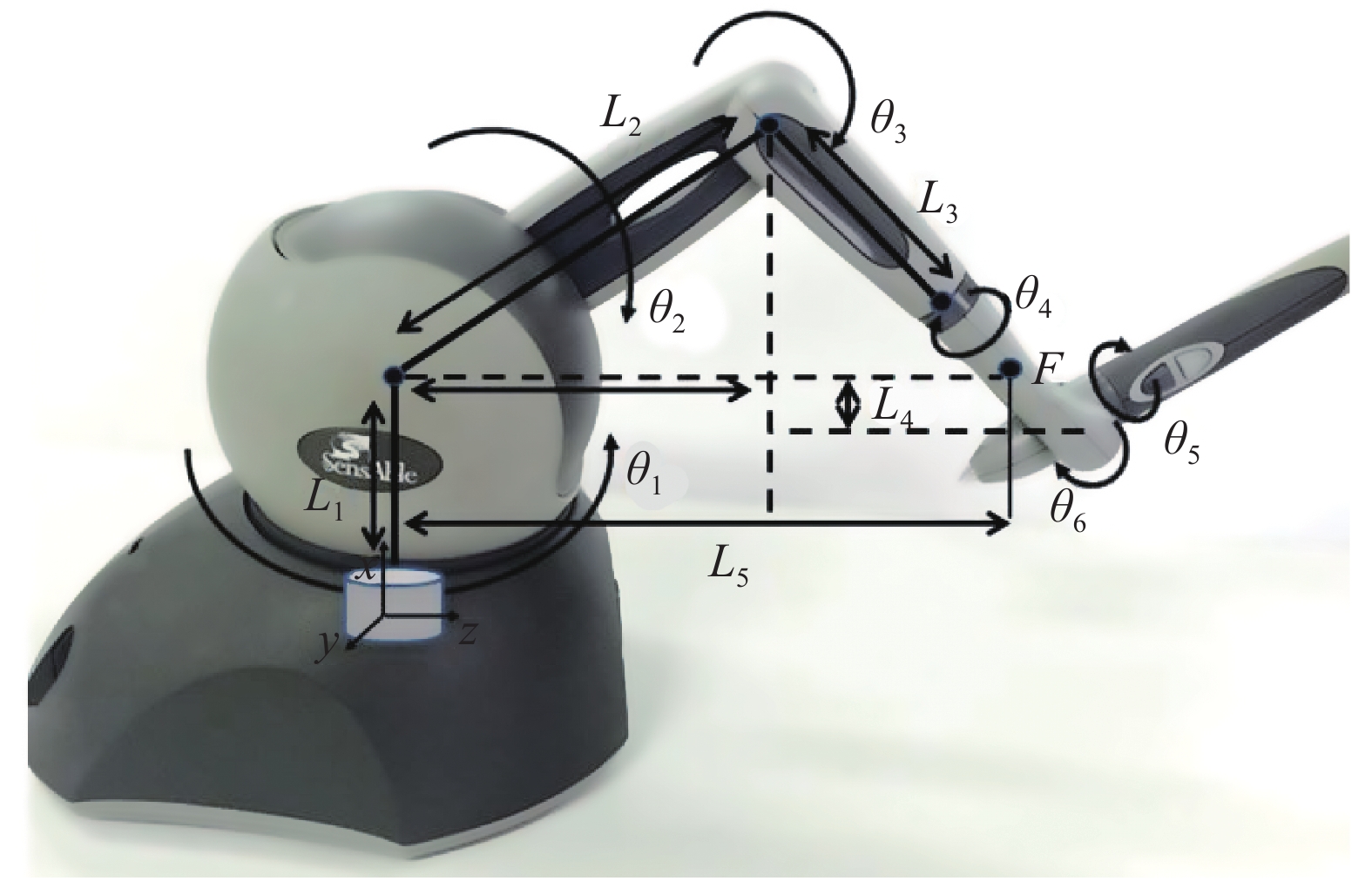
    Fig. 1. PHANTOM Omnistructure parameter diagram
    Kinematic modeling of the mobile robot
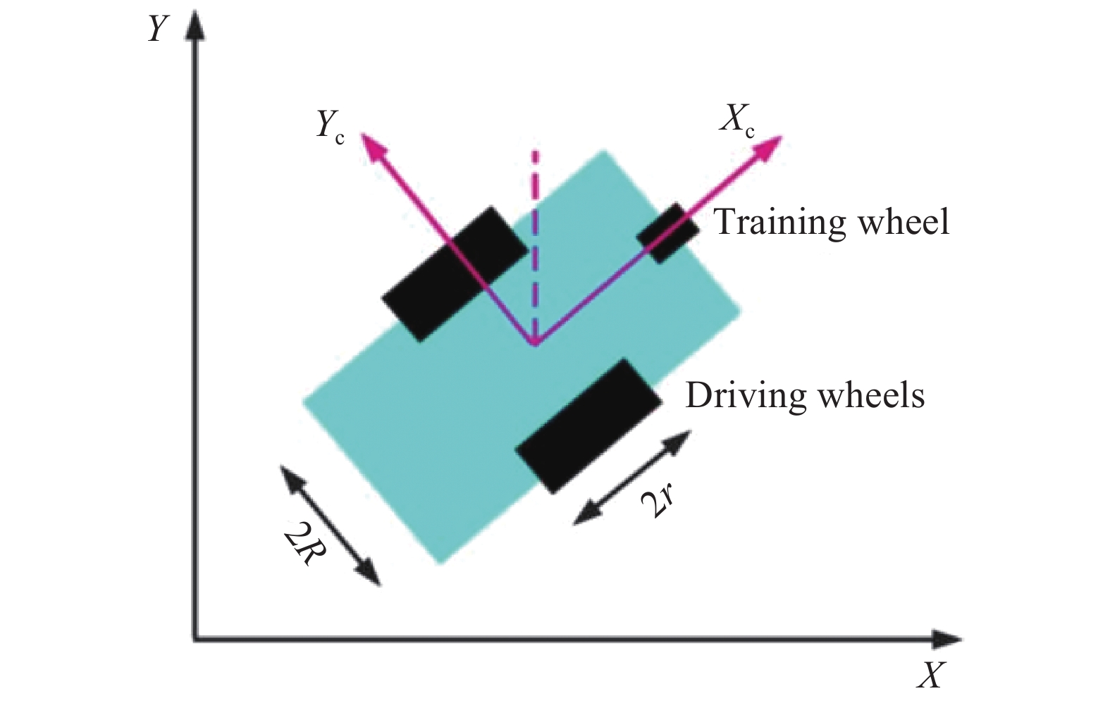
    Fig. 2. Kinematic modeling of the mobile robot
    Basic model of Smith predictor
    Fig. 3. Basic model of Smith predictor
    Time delay separating system of Smith predictor
    Fig. 4. Time delay separating system of Smith predictor
    Block diagram of system
    Fig. 5. Block diagram of system
    0.01 s delayed case
    Fig. 6. 0.01 s delayed case
    0.02 s delayed case
    Fig. 7. 0.02 s delayed case
    0.1 s delayed case
    Fig. 8. 0.1 s delayed case
    System block diagram of entire system
    Fig. 9. System block diagram of entire system
    GM (1,1) model predictive value
    Fig. 10. GM (1,1) model predictive value
    Force feedback conversion diagram
    Fig. 11. Force feedback conversion diagram
    Mobile robot
    Fig. 12. Mobile robot
    Experiment environment of mobile robot
    Fig. 13. Experiment environment of mobile robot
    Path trajectory of mobile robot in non-visible environment (curve)
    Fig. 14. Path trajectory of mobile robot in non-visible environment (curve)
    Distance between obstacle and mobile robot
    Fig. 15. Distance between obstacle and mobile robot
    Experimental environment of mobile robot(rectangular path)
    Fig. 16. Experimental environment of mobile robot(rectangular path)
    Path trajectory of mobile robot in non-visual environment (rectangular)
    Fig. 17. Path trajectory of mobile robot in non-visual environment (rectangular)
    Distance between mobile robot and obstacle (rectangular)
    Fig. 18. Distance between mobile robot and obstacle (rectangular)
    Number of jointsZaxis rotation angle Distance between common perpendicularsJoint offsetJoint torsional
    $\theta $$d$$a$$\alpha $
    1$\theta _1^{\rm{*}}$${d_1}$0$ - {90^ \circ }$
    2$\theta _2^{\rm{*}}$0${a_2}$0
    3$\theta _3^{\rm{*}}$0${a_3}$0
    Table 1. D-H parameter table of the PHANTOM Omni structure
    ParameterMeaning of parameters
    $m$Mass of mobile robots( $5.61 \;\rm kg$
    $I$Moment of inertia of mobile robot( $0.05 \;\rm kg{n^2}$
    $2R$Distance between two driving wheels( $0.290\;\rm m$
    $r$Driving wheel radius( $0.075\;\rm m$
    $O,X,Y$Spatial coordinates
    $C,{X_c},{Y_c}$Coordinates of the mobile robot
    $X,Y$Center position of the mobile robot in Cartesian coordinates
    $\theta $Angle between $X$ and ${X_c}$
    Table 2. Parameters table of the mobile robot
    Fenggang Liu, Lei Ding, Li Xiao. Remote control robot system based on predictive algorithm[J]. Infrared and Laser Engineering, 2021, 50(S2): 20210109
    Download Citation