• Acta Optica Sinica
  • Vol. 38, Issue 6, 0606008 (2018)
Jian Chen1、2, Qingqing Huang1、2, Qianwu Zhang1、2、*, Teng Wang1、2, Xianglong Zeng1、2, Yingxiong Song1、2, Yingchun Li1、2, and Junjie Zhang1、2
Author Affiliations
  • 1 Shanghai Institute for Advanced Communication and Data Science, Shanghai 200444, China
  • 2 Shanghai University Key Laboratory of Specialty Optics and Optical Access Networks, Shanghai University, Shanghai 200444, China
  • show less
    DOI: 10.3788/AOS201838.0606008 Cite this Article Set citation alerts
    Jian Chen, Qingqing Huang, Qianwu Zhang, Teng Wang, Xianglong Zeng, Yingxiong Song, Yingchun Li, Junjie Zhang. Orthogonal Frequency Division/Mode Division Multiplexing IM-DD Multimode Fiber Transmission System Based on Photonic Lanterns[J]. Acta Optica Sinica, 2018, 38(6): 0606008 Copy Citation Text show less
    Photonic lantern and its mode conversion
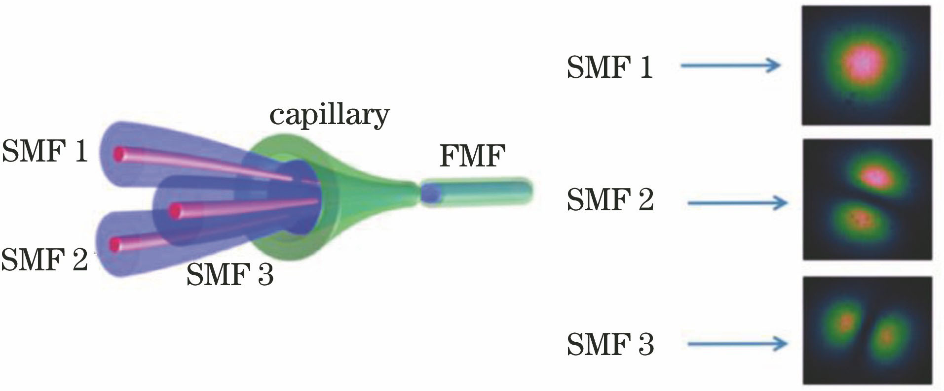
    Fig. 1. Photonic lantern and its mode conversion
    Peak-to-peak value of received signals amplitude. (a) Value for LP01; (b) value for LP11a; (c) adjusted value for LP01; (d) adjusted value for LP11a
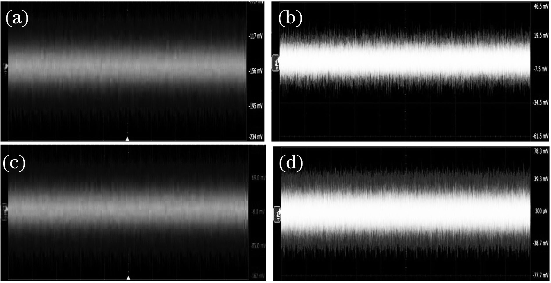
    Fig. 2. Peak-to-peak value of received signals amplitude. (a) Value for LP01; (b) value for LP11a; (c) adjusted value for LP01; (d) adjusted value for LP11a
    Structure of IM-DD OFDM experimental system
    Fig. 3. Structure of IM-DD OFDM experimental system
    Subcarrier bit allocation profile for OFDM signals
    Fig. 4. Subcarrier bit allocation profile for OFDM signals
    Relationships between transmitted optical power and BER for one-channel signal. (a) BTB; (b) over OM4 MMF with the length of 50 m
    Fig. 5. Relationships between transmitted optical power and BER for one-channel signal. (a) BTB; (b) over OM4 MMF with the length of 50 m
    Relationships between transmitted optical power and BER for two-channel signals. (a) Same transmitted optical power; (b) different transmitted optical powers
    Fig. 6. Relationships between transmitted optical power and BER for two-channel signals. (a) Same transmitted optical power; (b) different transmitted optical powers
    Constellations of the subcarriers at receiving port. (a) LP01 port; (b) LP11a port
    Fig. 7. Constellations of the subcarriers at receiving port. (a) LP01 port; (b) LP11a port
    Receiving portSending port
    LP01 portLP11a portLP11b port
    LP01 port-16.5-27.2-29.5
    LP11a port-29.1-21.5-20.1
    LP11b port-28.1-20.9-22.1
    Table 1. Insertion losses of photonic lanterndBm
    ParameterValueParameterValue
    Modulation format32/16/4 QAMPIN detector bandwidth /GHz1.5
    IFFT/FFT size64 pointsFiber typeOM4
    OFDM symbols per frame100 symbolsLaser wavelength /nm1550
    Cyclic prefix length16 pointsAWG sampling rate /( GSa·s-1)2
    DFB driving voltage2.1VppDSO sampling rate /( GSa·s-1)10
    MMF length /m50Laser bandwidth /GHz1.4
    Amp /dB10DC voltage /V12
    Table 2. Experimental system parameters
    Jian Chen, Qingqing Huang, Qianwu Zhang, Teng Wang, Xianglong Zeng, Yingxiong Song, Yingchun Li, Junjie Zhang. Orthogonal Frequency Division/Mode Division Multiplexing IM-DD Multimode Fiber Transmission System Based on Photonic Lanterns[J]. Acta Optica Sinica, 2018, 38(6): 0606008
    Download Citation