Abstract
We report a strict non-blocking four-port optical router that is used for a mesh photonic network-on-chip on a silicon-on-insulator platform. The router consists of eight silicon microring switches that are tuned by the thermo-optic effect. For each tested rousting state, the signal-to-noise ratio of the optical router is larger than 13.8 dB at the working wavelength. The routing functionality of the device is verified. We perform 40 Gbps nonreturn to zero code data transmission on its 12 optical links. Meanwhile, data transmission using wavelength division multiplexing on eight channels in the C band (from 1525 to 1565 nm) has been adopted to increase the communication capacity. The optical router’s average energy efficiency is 25.52 fJ/bit. The rising times (10% to 90%) of the eight optical switch elements are less than 10μs and the falling times (90%–10%) are less than 20μs.We report a strict non-blocking four-port optical router that is used for a mesh photonic network-on-chip on a silicon-on-insulator platform. The router consists of eight silicon microring switches that are tuned by the thermo-optic effect. For each tested rousting state, the signal-to-noise ratio of the optical router is larger than 13.8 dB at the working wavelength. The routing functionality of the device is verified. We perform 40 Gbps nonreturn to zero code data transmission on its 12 optical links. Meanwhile, data transmission using wavelength division multiplexing on eight channels in the C band (from 1525 to 1565 nm) has been adopted to increase the communication capacity. The optical router’s average energy efficiency is 25.52 fJ/bit. The rising times (10% to 90%) of the eight optical switch elements are less than 10μs and the falling times (90%–10%) are less than 20μs.Introduction
The performance of chip multiprocessors (CMPs) is governed not only by the performance of each processor core but also by their communication efficiency. As more and more processor cores are being integrated in one chip, traditional electrical interconnects have gradually become an obstacle to improving the performance of CMP because of their relatively low bandwidth, large power consumption and high delay[1-3]. Optical interconnects are a promising solution to this problem.
Several topologies for photonic networks-on-chip (NoC) have been widely investigated, including Mesh, Fat-Tree, Clos, and Crossbar[4-7]. Among them, the Mesh photonic NoC has received much attention because of its symmetric architecture, simple routing algorithm and good scalability. As one of the building blocks of the Mesh photonic NoC, the four-port optical router has received much attention. Compared with reconfigurable non-blocking optical router, a strict non-blocking optical router can be made more flexible for the network architecture and routing algorithm by adding more switching elements, and thus more routing choices. Various microring optical switches that are based four-port optical routers[8-22] have been reported because they have a small footprint and low power consumption.
In this paper, we report a strict non-blocking four-port silicon optical router on a silicon-on-insulator (SOI) platform for a Mesh photonic NoC. It consists of eight microring optical switches tuning with thermo-optic effect. Furthermore, 8 × 40 Gbps data transmission utilizing wavelength division multiplexing (WDM) has been carried out through all of its 12 optical links in the C band.
Topology and principle
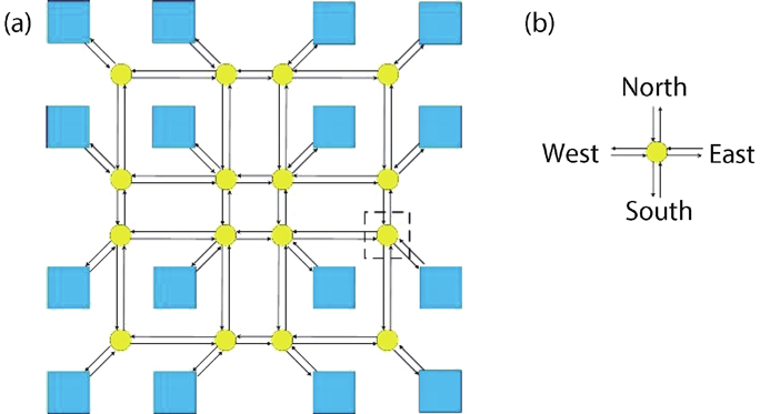
Fig. 1(a) shows the schematics of a 16-core CMP with a 4 × 4 2D mesh photonic network linking 16 different processor cores. To ensure bidirectional transmission on the same link, each optical link has two unidirectional waveguides. A four-port optical router (seeFig. 1(b)) is located at the four edges of the Mesh photonic NoC, connecting four directions: East, West, South, and North. The OE/EO interfaces connect one port of the optical router to a local electronic block, while the other three ports are connected to three additional optical routers.
| Input port |
|---|
| East | South | West | North |
|---|
| Outputport | East | – | →S7(B)→ | →S8(C)→S6(B)→S7(C)→ | →S2(C)→S5(C)→S6(C)→S7(C)→ |
| South | → S1(C)→S3(C)→S5(C)→S8(C)→ | – | →S8(B)→ | →S2(C)→S5(B)→S8(C)→ |
| West | →S1(C)→S3(B)→S2(C)→ | →S7(C)→S4(C)→S3(C)→S2(C)→ | – | →S2(B)→ |
| North | →S1(B)→ | →S7(C)→S4(B)→S1(C)→ | →S8(C)→S6(C)→S4(C)→S1(C)→ | – |
Table 0. The 12 optical links of the strict non-blocking four-port optical router.

Figure 1.(Color online) Schematics of (a) 2D Mesh network of a 16-core CMP and (b) four-port optical router. The blue squares indicate processor cores, yellow dots indicate optical routers, and lines with arrows indicate optical waveguides.
Fig. 2(a) shows the architecture of the four-port optical router. The eight microring optical switches are denoted as Sj (j = 1, 2, ..., 8). As displayed inFig. 2(b), when the microring is on-resonance at its working wavelength, the optical switch Sj is in the “bar” state; and when the microring is off-resonance at its working wavelength, the optical switch Sj is in the “cross” state. We have denoted the microring optical switch in the “bar” state as Sj(B) and the one in the “cross” state as Sj(C). The optical link from input port P (East, West, South, and North) to output port Q is marked as Pi → Qo (e.g., the optical link from the East input port to the South output port is marked as Ei → So). The optical route from the East input port to the South output port is denoted as Ei → S1(C) → S3(C) → S5(C) → S8(C) → So.
Figure 2.(Color online) Schematics of (a) the optical router and (b) the microring optical switch.
The input and output port in the same direction (East, West, South and North) are associated to the same node, and the connection between them has no sense. Therefore, this four-port strict non-blocking optical router contains 12 effective optical links in total. These connections can be controlled by a routing algorithm (shown inTable 1), which enables four parallel optical links for arbitrary one-to-one interconnection from any of the four input ports to any of other three output ports simultaneously without contention at the working wavelength.
Fabrication and experiment
The optical router is fabricated at AMF’s silicon photonics foundry and the design is defined using 248-nm-deep ultra-violet photolithography. The waveguide exclusively supporting the fundamental quasi-TE mode is a rib type, which has a height of 220 nm, a width of 400 nm, and a slab thickness of 70 nm. An inductively coupled plasma etching process is adopted to etch the top silicon layer. To prevent optical loss caused by metal absorption, plasma-enhanced chemical vapor deposition (PECVD) is used to form a 1500-nm-thick silica layer on the silicon waveguide. Then, on a separate layer, titanium nitride with 220 nm thickness is sputtered, and titanium nitride heaters with 1µm width are fabricated by UV photolithography and dry etching. Via holes are carved following the deposition of a 300-nm-thick silica layer by PECVD. Eventually, aluminum pads are created.Fig. 3 shows a micrograph of the fabricated optical router, which has a footprint of 400 × 450µm2.
Figure 3.(Color online) Micrograph of the fabricated optical router.
| Input port |
|---|
| East | South | West | North |
|---|
| Outputport | East | – | →S7(B)→ | →S8(C)→S6(B)→S7(C)→ | →S2(C)→S5(C)→S6(C)→S7(C)→ |
| South | → S1(C)→S3(C)→S5(C)→S8(C)→ | – | →S8(B)→ | →S2(C)→S5(B)→S8(C)→ |
| West | →S1(C)→S3(B)→S2(C)→ | →S7(C)→S4(C)→S3(C)→S2(C)→ | – | →S2(B)→ |
| North | →S1(B)→ | →S7(C)→S4(B)→S1(C)→ | →S8(C)→S6(C)→S4(C)→S1(C)→ | – |
Table 0. The 12 optical links of the strict non-blocking four-port optical router.
The eight microring optical switches are constructed with identical parameters, resulting in the same resonance wavelength. Increasing the radius of the microring optical switch, for example, can improve its aggregate bandwidth, while simultaneously expanding its footprint. The radii of the microring are chosen to be 20µm as a tradeoff between device size and aggregate bandwidth.
Fig. 4 shows the measured transmission spectra of the microring switch element on its “cross” and “bar” states. The coupling loss between the device and the lensed fiber is about 2.5 dB/facet. It is easy to determine the insertion loss is 0.8 dB for the optical link I2–O1 at the working wavelength when the microring switch element is on the “cross” state. The insertion loss is 1.8 dB for the optical link I2–O2 at the working wavelength when the microring switch element is on the “bar” state. The extinction ratios of the optical links of the microring switch on its two statuses are larger than 17 dB at the working wavelength.
Figure 4.(Color online) Static spectral responses of the microring switch element on its “cross” and “bar” states.
To verify its routing operation, three routing states of the optical router, which cover all its 12 optical links and 12 particular routing paths, are chosen to form an independent test scenario.Table 2 displays the states of the eight microring optical switches in the three routing states that were chosen. The letter “B” or “C” inTable 2 indicates that the associated microring optical switch is in the “bar” or “cross” states, which correspond to on-resonance or off-resonance at the working wavelength, respectively.
To characterize the spectral responses of the optical router and identify the operating wavelength, an optical spectrum analyzer and an amplified spontaneous emission source are used. We measure the transmission spectra of the four specific optical links Ei → So, Si → Wo, Wi → No and Ni → Eo. The transmission spectra show that the working wavelength is near 1547 nm.
The microring can manipulate eight wavelength channels in the C band because it has a radius of 20μm, which is equivalent to an FSR of around 5 nm. The extinction ratios of the microring optical switches at their through and drop ports are approximately 27 and 15 dB. The drop port's 3-dB bandwidth is 0.59 nm (about 73.8 GHz), which is sufficient for 40 Gbps data transmission. The resonance wavelengths of the eight microring optical switches are a little separated due to a manufacturing error, which could be adjusted by using thermo-optic tuning at the expense of increased power consumption.
Tunable voltage sources are applied to change the resonance wavelengths of the mircorings to measure the optical signal-to-noise ratio (SNR) of the optical router.Fig. 5 displays the optical router's spectral responses of its three routing stages. For routing state 1, all microring optical switches are off-resonance at the working wavelength and four optical links Ei → So, Si → Wo, Wi → No, and Ni → Eo are established. For example, the purple line in the first graph represents the spectral response of the optical link Ni → Eo and the rest three lines represent the spectral responses of the optical links Ei → Eo, Si → Eo, and Wi → Eo, which are noises to the optical link Ni → Eo, as they are not formed in routing state 1. The average optical SNRs of the optical router exceed 13.8 dB. Improving the extinction ratios of the microrings and the optical crosstalks of the waveguide crossings may further increase the optical SNRs of the router.
Figure 5.(Color online) Optical SNRs of the four-port optical router in the selected three routing states, which cover its all 12 optical links. Each row represents a single routing state with identical output port in each column. Notation P represents the overall power consumption of each routing state.
A tunable laser and a Mach-Zehnder modulator are employed to provide external data to verify the functionality of data transmission. A pulse pattern generator generates a 40 Gbps 231–1 pseudo-random bit sequence (PRBS). After being amplified by an erbium-doped fiber amplifier, the output optical signals are sent to a digital communication analyzer (DCA) for viewing the eye diagrams (seeFig. 6). It should be noted that all eye diagrams are captured with a single channel data transmission. The extinction ratio of the optical signal is 18.2 dB for back-to-back data transmission and about 16.4 dB for data transmission through the device. For the 12 optical links of the four-port optical router, open and clear eye diagrams validate the 40 Gbps the data transmission function.
Figure 6.(Color online) For all 12 optical links, eyes diagrams at corresponding output ports, 40 Gbps 231–1 PRBS optical signal at wavelength 1547.37 nm is used.
As aforementioned, the microring optical switch has a periodic spectral response. As a result, wavelength division multiplexing (WDM) technology can be used to raise the aggregate bandwidth of microring optical switches based four-port optical router without modifying the routing algorithm or expending additional electrical power. WDM data transmission for the optical router is performed to validate this property. For simplicity, the result on a typical optical link Ei → So is shown inFig. 7. Eight optical signals at various wavelengths with interval equals to the FSR of the microring optical switches can be multiplexed in the whole C band. Because of the dispersion of silicon waveguide, the adjacent channel spacing is slightly different. The WDM data transmission of the optical router is validated by the open and clear eye diagrams.
Figure 7.(Color online) WDM data transmission through the optical link Ei → So.
The power consumption of the eight microring optical switches in the “bar” and “cross” states are measured. The switch elements in the “cross” state do not consume electrical power. The power consumption of the switches (
) in the “bar” state are 12.2, 10.6, 11.8, 12.4, 11.3, 14.0, 13.2, and 12.5 mW, correspondingly. With the assumption that every routing state appears with the same chance, the device’s average power consumption is 32.67 mW/routing state. For each optical link, the communication capacity is 320 Gbps, and the optical router can manage four optical links at the same time. As a result, the average energy efficiency of the device is 25.52 fJ/bit. We use a 10 kHz square wave to tune the state of the optical switch and test its response time. Note that the rising and falling time are defined for the through port of the microring optical switch. The 90% to 10% falling time of each optical switch fluctuates from 13 to 17µs and the 10% to 90% rising time fluctuates from 2 to 9µs.
Conclusion
In summary, we have demonstrated a strict non-blocking four-port optical router composed of eight microring optical switches. Furthermore, 8 × 40 Gbps data transmission has been achieved over all its 12 optical links in the whole C band. All 12 optical links in the characterized routing states have optical SNRs greater than 13.8 dB.
Acknowledgements
This work was supported by National Key Research and Development Program of China (2019YFB2203602) and National Science Fund for Distinguished Young Scholars (61825504).
References
[1] R G Beausoleil, P J Kuekes, G S Snider et al. Nanoelectronic and nanophotonic interconnect. Proc IEEE, 96, 230(2007).
[2] D A B Miller. Device requirements for optical interconnects to silicon chips. Proc IEEE, 97, 1166(2009).
[3] C Batten, A Joshi, J Orcutt et al. Building manycore processor-to-DRAM networks with monolithic silicon photonics. 16th IEEE Symposium on High Performance Interconnects(2008).
[4] H X Gu, J Xu, W Zhang. A low-power fat tree-based optical network-on-chip for multiprocessor system-on-chip. Design, Automation & Test in Europe Conference & Exhibition(2009).
[5] A Joshi, C Batten, Y J Kwon et al. Silicon-photonic clos networks for global on-chip communication. 3rd ACM/IEEE International Symposium on Networks-on-Chip(2009).
[6] H X Gu, K H Mo, J Xu et al. A low-power low-cost optical router for optical networks-on-chip in multiprocessor systems-on-chip. IEEE Computer Society Annual Symposium on VLSI(2009).
[7] N Sherwood-Droz, H Wang, L Chen et al. Optical 4 × 4 hitless silicon router for optical Networks-on-Chip (NoC). Opt Express, 16, 15915(2008).
[8] A Kamierczak, W Bogaerts, E Drouard et al. Highly integrated optical 4 × 4 crossbar in Silicon-on-Insulator technology. IEEE J Lightwave Technol, 27, 3317(2009).
[9] R Q Ji, L Yang, L Zhang et al. Five-port optical router for photonic networks-on-chip. Opt Express, 19, 20258(2011).
[10] Y Ye, X W Wu, J Xu et al. Holistic comparison of optical routers for chip multiprocessors. IEEE International Conference on Anti-counterfeiting, Security, and Identification(2012).
[11] J Chan, A Biberman, B G Lee et al. Insertion loss analysis in a photonic interconnection network for on-chip and off-chip communications. 21st Annual Meeting of the IEEE Lasers and Electro-Optics Society (LEOS 2008)(2008).
[12] N B Renani, E Yaghoubi, N Sadehnezhad et al. NLR-OP: a high-performance optical router based on North-Last turning model for multicore processors. J Supercomput, 78, 2442(2022).
[13] P P Dang, C T Li, W X Zheng et al. Non-blocking four-port optical router based on thermooptic silicon microrings. Optoelectron Lett, 12, 268(2016).
[14] H W Rhee, J B You, H Yoon et al. 32 Gbps data transmission with 2D beam-steering using a silicon optical phased array. IEEE Photonics Technol Lett, 32, 803(2020).
[15] H Jia, T Zhou, S Yang et al. Five-port non-blocking silicon optical router based on mode-selective property. 18th International Conference on Optical Communications and Networks (ICOCN), 1(2019).
[16] M Geng, Z Tang, K Chang et al. N-port strictly non-blocking optical router based on Mach-Zehnder optical switch for photonic networks-on-chip. Opt Commun, 383, 472(2017).
[17] L I Xia, X Q Jiang, X F Wang. A 4 × 4 non-blocking wavelength selective router based on cascaded two-ring resonators. J Optoelectron Laser, 30, 678(2019).
[18] T Surenkhorol, H Kishikawa, N Goto. Integrated-optic circuit for optical 8QAM coded label recognition in photonic router. Integrated Photonics Research, Silicon & Nanophotonics(2017).
[19] S Mohamed, L Shahada, M Swillam. Vertical silicon nanowires based directional coupler optical router. IEEE Photonics Technol Lett, 30, 789(2018).
[20] O A Kalange, B B Ladniya, R R Kothari et al. Design and analysis of five port optical router for optical NoC. 2018 International Conference on Inventive Research in Computing Applications (ICIRCA)(2018).
[21] Q Cheng, Y D Liang, M Bahadori et al. Si/SiN microring-based optical router in switch-and-select topology. 2018 European Conference on Optical Communication (ECOC)(2018).
[22] Z Ge, L Zhang, G Wang et al. On-chip router elements based on silicon hybrid plasmonic waveguide. IEEE Photonics Technol Lett, 29, 952(2017).