• Photonics Research
  • Vol. 5, Issue 4, 315 (2017)
J. M. Sarraute1、2、*, K. Schires1, S. LaRochelle2, and F. Grillot1、3
Author Affiliations
  • 1LTCI, Télécom Paristech, Université Paris-Saclay, 46 rue Barrault, 75013 Paris, France
  • 2COPL, Université Laval, 2375 rue de la Terrasse, Québec, Québec G1V 06A, Canada
  • 3Center for High Technology Materials, University of New Mexico, 1313 Goddard SE, Albuquerque, New Mexico 87106-4343, USA
  • show less
    DOI: 10.1364/PRJ.5.000315 Cite this Article Set citation alerts
    J. M. Sarraute, K. Schires, S. LaRochelle, F. Grillot. Effects of gain nonlinearities in an optically injected gain lever semiconductor laser[J]. Photonics Research, 2017, 5(4): 315 Copy Citation Text show less
    (a) Schematic of the two-section GL laser (framed by black dotted square). Evolution of the material gain with the carrier density in both sections (left). Ga,b′ are the differential gains in each section. (b) Schematic of the OIL configuration.
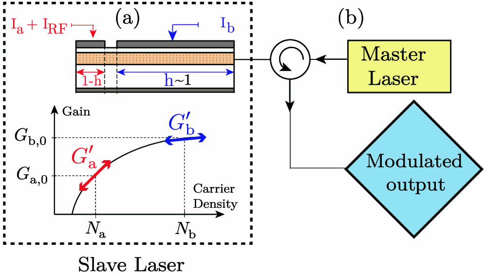
    Fig. 1. (a) Schematic of the two-section GL laser (framed by black dotted square). Evolution of the material gain with the carrier density in both sections (left). Ga,b are the differential gains in each section. (b) Schematic of the OIL configuration.
    MTF of the free-running laser without GL calculated from 5 for ϵ=0,5×10−17,10−16,and 5×10⁻¹⁶ cm3.
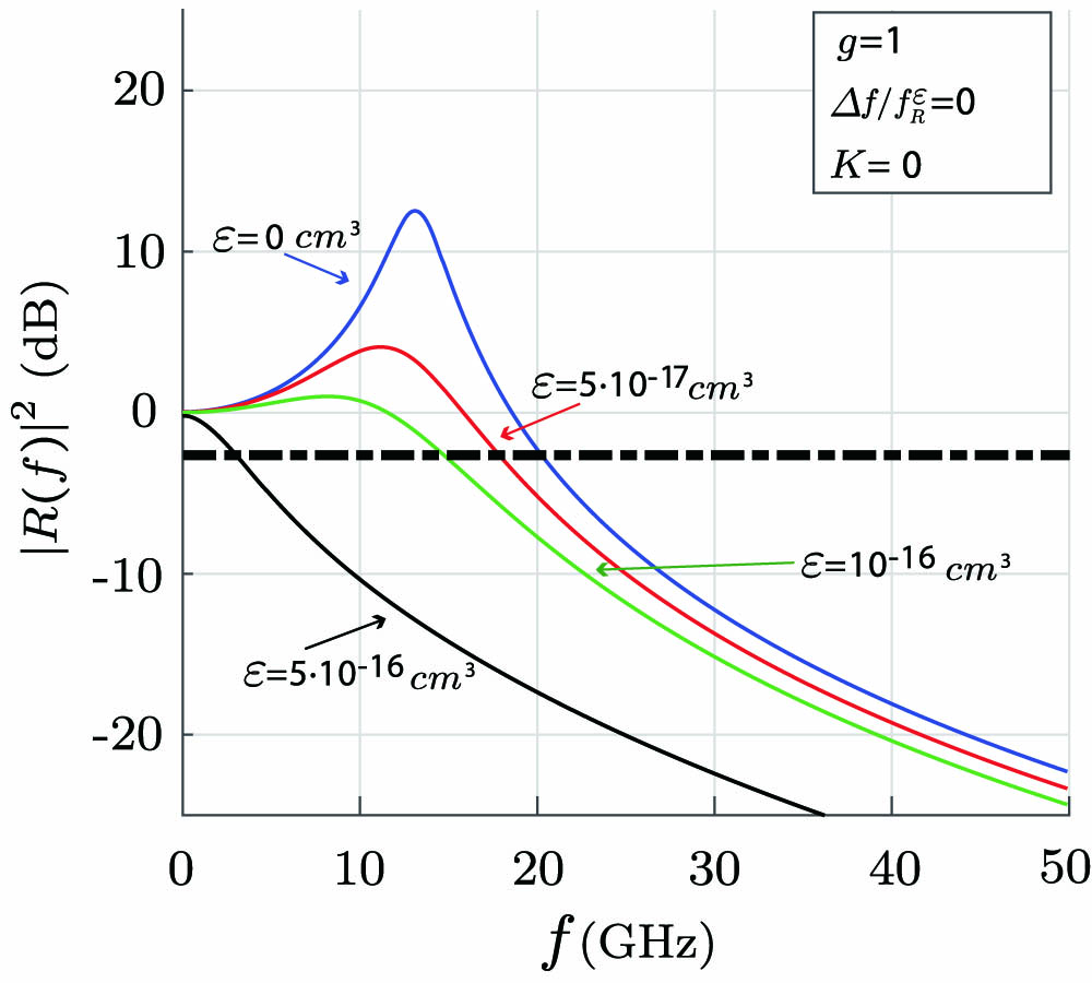
    Fig. 2. MTF of the free-running laser without GL calculated from 5 for ϵ=0,5×1017,1016,and  5×1016cm3.
    MTF of the OIGL laser calculated from 3 for different values of gain compression ϵ=0,10−17,5×10⁻¹⁷,and 10−16 cm3 and with a GL of g=10. The injected power and frequency detuning are (a) K=3.5,Δf/fR=0.97 and (b) K=8,Δf/fR=3.3. Red dotted curves represent the MTF for the free-running case assuming no compression and without GL.
    Fig. 3. MTF of the OIGL laser calculated from 3 for different values of gain compression ϵ=0,1017,5×1017,and  1016cm3 and with a GL of g=10. The injected power and frequency detuning are (a) K=3.5,Δf/fR=0.97 and (b) K=8,Δf/fR=3.3. Red dotted curves represent the MTF for the free-running case assuming no compression and without GL.
    3 dB bandwidth in the stable-locking region of the OIGL laser with g=10 and ϵ=10−16 cm3.
    Fig. 4. 3 dB bandwidth in the stable-locking region of the OIGL laser with g=10 and ϵ=1016  cm3.
    Evolution of the 3 dB bandwidth with respect to GL strength and gain compression factor for (a) K=0 and (b) K=8.
    Fig. 5. Evolution of the 3 dB bandwidth with respect to GL strength and gain compression factor for (a) K=0 and (b) K=8.
    Simulation parametersSymbolsValue
    Cavity volumeV2×1017  m3
    Bias currentIa/b18/1.8  mA
    Steady-state optical gainG0,b1.8×1013  s1
    Optical confinementΓ0.032
    Transparency carrier densityNtr1.8×1024  m3
    Fitting parameterNs0.4×1024  m3
    Carrier lifetimeτc1.57×109  s
    Photon lifetimeτp2.77×1012  s
    Linewidth enhancement factorαH2
    Coupling S-M factorkc1×1011  s1
    Damping rate ratiog1.15–10
    Injection strengthK−15 to +10 dB
    Gain compression factorϵ05×1016  cm3
    Spontaneous emission factorβ105
    Table 1. Material and Laser Parameters
    J. M. Sarraute, K. Schires, S. LaRochelle, F. Grillot. Effects of gain nonlinearities in an optically injected gain lever semiconductor laser[J]. Photonics Research, 2017, 5(4): 315
    Download Citation