J. M. Sarraute1,2,*, K. Schires1, S. LaRochelle2, and F. Grillot1,3
Abstract
The effects of gain compression on the modulation dynamics of an optically injected gain lever semiconductor laser are studied. Calculations reveal that the gain compression is not necessarily a drawback affecting the laser dynamics. With a practical injection strength, a high gain lever effect and a moderate compression value allow us to theoretically predict a modulation bandwidth four times higher than the free-running one without a gain lever, which is of paramount importance for the development of directly modulated broadband optical sources compatible with short-reach communication links.1. INTRODUCTION
As future optical networks prepare to operate at 100 Gbps and beyond, the development of small footprint optoelectronic devices with high-speed performances is required, in particular for short-reach communication links such as access and datacenter optical networks [1,2]. Although complex modulation formats combined with digital signal post-processing architectures can be used to reach ultra-high modulation bandwidth, the long latency introduced by the electronic processing also can result in a severe communication bottleneck [3]. To this end, direct-detection systems implemented with directly modulated lasers (DMLs) can still provide a simple and compact solution for the development of low-cost fiber optic communications [4]. In order to keep increasing data rates, it is necessary to enhance the modulation dynamics of optical transmitters without creating other impairments such as intensity noise and frequency chirping. Over the last past years, it has been shown that the modulation dynamics can be improved either by the development of novel in-plane semiconductor materials [5,6] or by using nonlinear architectures, including optical injection-locking (OIL) [7–9] and gain lever (GL) [10]. However, taken separately, both GL and OIL can produce effects undesired for applications where flat modulation frequency responses are desired: GL increases the amplitude of the response while OIL can, on the other hand, lead to the occurrence of dips that limit the 3 dB bandwidth [11]. Recently, it was shown both theoretically and experimentally that optically injected gain lever (OIGL) semiconductor lasers can be a promising solution where the drawbacks of OIL and GL balance each other, hence leading to larger modulation bandwidths well beyond the relaxation oscillation frequency (ROF) of the free-running laser [11]. For instance, a three-times-enhanced modulation bandwidth has been experimentally reported on an injection-locked GL distributed feedback (DFB) laser [12]. However, the gain compression originating from both the carrier heating and the spectral hole burning is known to strongly affect the modulation properties of DMLs [13]. Following the same semi-analytical approach as the one used in Ref. [11], this paper aims at investigating the effects of the gain compression on the modulation dynamics of OIGL lasers. Surprisingly, calculations reveal that gain compression does not have a significant impact on the modulation performances of the OIGL semiconductor laser and can even be used to effectively tailor the modulation response. This result is drastically different from the free-running GL laser or the OIL laser without GL. With a practical injection strength, a high GL effect and a moderate compression factor of , which is a typical value encountered in quantum dot semiconductor materials, calculations predict a modulation bandwidth as high as 85 GH, which is four times higher than the free-running case. Consequently, this work provides selection rules that can be used as manufacturing guidelines for the development of broadband transmitters for short-reach optical networks.
2. RATE EQUATIONS
As shown in Fig. 1(a) (framed by black dotted square), the GL laser is composed of two electrically isolated sections sharing the same active area. The GL effect depends on the cavity length ratio and the current ratio of each section. First, in order to ensure the GL effect, the shorter section (with a length of ) is pumped close to the optical transparency at a bias (to which the modulation is added through ), such that its steady-state optical gain () remains close to zero. On the other hand, the larger section (with length of ) is pumped under continuous waves (CW) well above the lasing threshold such that its steady-state optical gain () remains near the threshold value () and its differential gain () is lower than the one in the shorter section (). In addition, the fractional length of the larger section is taken close to unity to ensure the GL effect. This large difference between the differential gains of each section () produces a significant change of the carrier density in the larger section with only a small variation of current in the modulation in the shorter section. Figure 1(b) schematically represents the two-section GL combined with the OIL configuration. The latter involves two optical sources, referred to as the master laser (ML) and the slave laser (SL) (in the present case, the GL represented by the black dotted square). The light output from the ML is injected into the SL cavity. The two relevant parameters for OIL are the frequency detuning between the ML and SL, noted such as , where is the lasing frequency of the ML or the free-running SL and the injected power in the SL cavity is . These scale with the characteristics of the free-running SL, i.e., its ROF and output power noted and , respectively. The ratios and are thus used to compare the results obtained with different lasers, as long as the initial conditions remain the same.
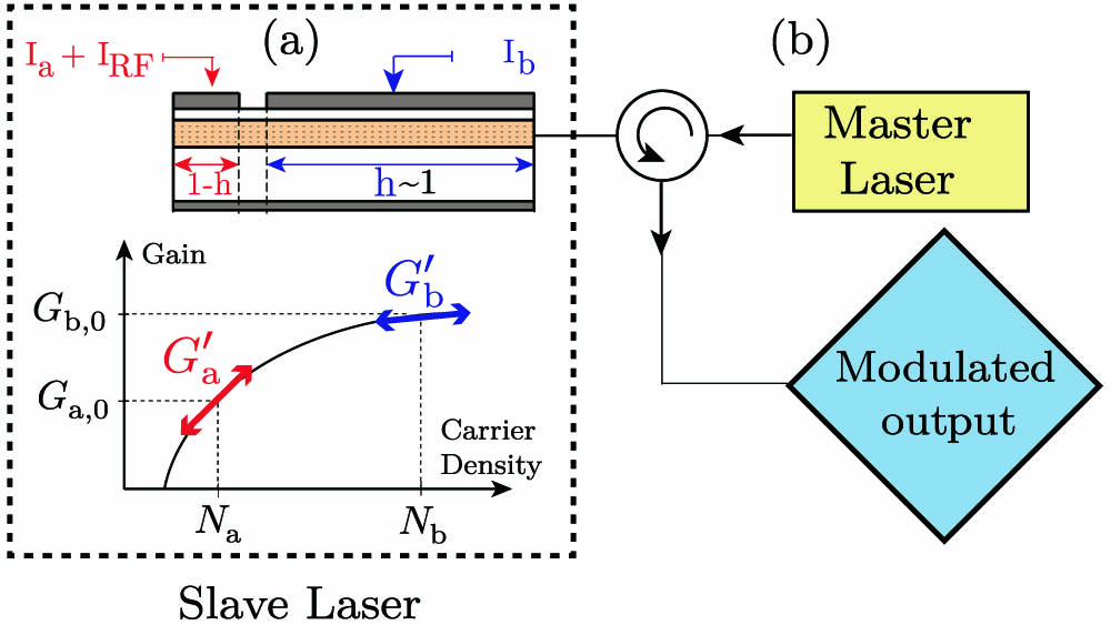
Figure 1.(a) Schematic of the two-section GL laser (framed by black dotted square). Evolution of the material gain with the carrier density in both sections (left). are the differential gains in each section. (b) Schematic of the OIL configuration.
The analysis of the OIGL laser is described using a set of differential rate equations, as in Ref. [11], including one for carrier density in each section, one for photon density, and the latest for the field phase. In this paper, the gain compression factor () is incorporated into the logarithmic gain such as [13] where represents the gain compression factor related to the photon density (), the carrier density at the transparency, the carrier density, and is the fitting parameter [13] and or . are the steady-state optical gains. Once the photon density into the cavity exceeds a certain value, fixed by the gain compression (typically of the order of ), the product becomes larger than the unity, and consequently gain nonlinearities become significant. Taking into account the nonlinear gain coefficient, the rate equation model is re-casted (see Ref. [11]) as follows: with being the current density, the carrier lifetime, and the unclamped material gain of section . In addition, is the photon lifetime of the SL cavity and corresponds to the linewidth enhancement factor. Regarding the optical injection, is the photon density injected into the SL with a coupling efficiency , a detuning , and a phase offset between the ML and SL . Finally, let us note that where is the fractional length of the larger section and is the optical confinement factor.
In Eq. (2b), represents the spontaneous emission rate, which is expressed as where is the spontaneous emission factor. In the numerical computations, is only used to extract the steady-state values. When the modulation dynamics are further analyzed, the spontaneous contribution is ignored because it does not play a dominant role in the operating conditions studied here [14].
As already described in Ref. [11], the modulation response of the OIGL can be derived from a small-signal analysis of the rate equations by considering , , , , and as dynamical variables such that where refers to one of the previous dynamical variables (except ), written as , being the continuous and the modulation part. Equation (3b) is obtained from deriving Eq. (1) with respect to and . The coefficient , which corresponds to the differential gain of the uncompressed material, is defined as the partial derivative of the gain with respect to carrier density: , where and are the steady-state solutions of the rate equations given in Eq. (2). Taking into account the compression factor, the differential gain is written as .
Under small-signal analysis and asymmetric-bias conditions ( and ), the set of rate equations could be written such as where is the matrix, including the partial derivative of each variables. The extraction of the modulation transfer function (MTF) is performed using Cramer’s rule. Finally, the normalized MTF of the OIGL laser including the gain compression is expressed as follows: where , and and Equation (5) is similar to the OIGL MTF without the gain compression [11]. Indeed, we obtain the same coefficients , and where the -coefficient, the damping rate factor , and the damping rate ratio become -dependent [Eq. (7)]. Indeed the damping rate factor, usually expressed as , is more complex. Additionally, four new -dependent coefficients are introduced , , , and . This semi-analytical resolution of the rate equations can now be used to identify the key parameters such as , , and controlling the modulation dynamics of OIGL lasers.
3. RESULTS AND DISCUSSION
Table 1 gives all the material and laser parameters used in the simulations [14] that are performed for three different conditions of optical injection, both with strong GL effect () and without (). The gain compression factor is varied between and [15]. In the following, the laser’s MTFs are depicted with respect to the modulation frequency. Because the gain compression induces a variation of the ROF, the latter denoted as is recalculated for each value of and then used to normalize the corresponding frequency detuning. However, in order to better follow the evolution of the 3 dB bandwidth, the MTF is plotted with respect to the modulation frequency instead of as in Ref. [11].
| Simulation parameters | Symbols | Value |
| Cavity volume | V | 2×10⁻¹⁷ m3 |
| Bias current | Ia/b | 18/1.8 mA |
| Steady-state optical gain | G0,b | 1.8×10¹³ s−1 |
| Optical confinement | Γ | 0.032 |
| Transparency carrier density | Ntr | 1.8×1024 m−3 |
| Fitting parameter | Ns | −0.4×1024 m−3 |
| Carrier lifetime | τc | 1.57×10⁻⁹ s |
| Photon lifetime | τp | 2.77×10⁻¹² s |
| Linewidth enhancement factor | αH | 2 |
| Coupling S-M factor | kc | 1×10¹¹ s−1 |
| Damping rate ratio | g | 1.15–10 |
| Injection strength | K | −15 to +10 dB |
| Gain compression factor | ϵ | 0−5×10⁻¹⁶ cm3 |
| Spontaneous emission factor | β | 10−5 |
Table 1. Material and Laser Parameters
First, the MTF of the free-running laser ( and ) without GL () is studied for different values of (Fig. 2). In what follows, normalized MTFs are considered in order to better compare the modulation bandwidth with respect to . Let us stress that using unnormalized MTFs instead would not affect the bandwidth predictions and the conclusions presented hereinafter. Figure 2 shows that the ROF decreases with from 13 GHz for (green) down to 0.8 GHz for (black). When the compression is too large, i.e., , the latter is heavily damped, making the 3 dB bandwidth extremely small (brown). Besides, as already reported in Ref. [15], the decrease of the ROF is also accompanied by a large diminution of the modulation bandwidth. For instance, between and , the 3 dB bandwidth is reduced by 25% from 20 to 15 GHz. Finally, it is important to stress that the peak of the modulation response is also drastically reduced from about 12 () to almost 0 dB (). This data set confirms that gain nonlinearities do substantially affect the modulation dynamics of a free-running laser without GL effect as previously reported [13,15].

Figure 2.MTF of the free-running laser without GL calculated from 5 for .
The next section investigates the modulation dynamics of the OIGL laser with respect to the configuration (, ). Overall, the numerical result shows that the OIGL laser is not that sensitive to the OIL parameters as long as the laser remains stably locked, which is vital to avoid the occurrence of any complex dynamics such as chaos or periodic oscillations.
In what follows, weak [ in Fig. 3(a)] and strong [ in Fig. 3(b)] injection cases are only considered both with activated GL (). The free-running case (red dotted) is used as the reference. As previously studied in Ref. [11], the combined effects of GL and OIL shift the response toward higher frequencies (OIL) and increase the amplitude of the modulation response (GL). The latter is particularly intense for . Indeed, as compared with the free-running without GL, it can be seen that the amplitude of the modulation response rises from 11 dB (solid blue curves in Fig. 2) to 30 dB for and . However, for both strong and weak injection, Fig. 3(b) reveals that, even with a relatively large gain compression value, the OIGL system is able to reach bandwidths up to 85 GHz for injection ratios approaching 10 dB. Besides, it also shows that the amplitude of the modulation response decreases from 30 dB for to 15 dB for and down to 10 dB for . This latest value of gain compression even results in an amplitude of the modulation response reaching values lower than that of the free-running without GL. In addition, instead of a 25% 3 dB bandwidth reduction as in the free-running without GL, only 4% are lost for both weak and strong injection. Indeed, for weak injection, the 3 dB bandwidth only decreases from 65 GHz for to 62 GHz for [Fig. 3(a)]. Similarly, for strong injection the 3 dB bandwidth only decreases from 88 to 84 GHz for and , respectively [Fig. 3(b)].
Figure 3.MTF of the OIGL laser calculated from 3 for different values of gain compression and with a GL of . The injected power and frequency detuning are (a) and (b) . Red dotted curves represent the MTF for the free-running case assuming no compression and without GL.
Figure 4 presents a mapping of the 3 dB bandwidth of the laser within the stable-locking region for and a gain compression of . It is interesting to note that, given the approximation of close to unity, the GL is assumed to have little effect on the injection-locking map. As gain compression changes the laser’s ROF, it thus slightly affects the locking region because the Hopf bifurcation (top boundary of the locking area) scales with the ROF. Simulations unveil the possibility to reach large 3 dB bandwidths within the stable-locking region of the OIGL laser with and .
Figure 4.3 dB bandwidth in the stable-locking region of the OIGL laser with and .
Finally, Fig. 5 shows the evolution of the 3 dB bandwidth as a function of gain compression and GL strength, without OIL and strongly injection-locked cases. For the free-running case [Fig. 5(a)], we see that the 3 dB bandwidth slightly increases with the GL, and, as previously indicated, it slowly decreases with increasing gain compression. We always denote an increase of the modulation bandwidth under injection-locking [Fig. 5(b)] according to the GL value. However, for each value of , the 3 dB bandwidth does not decrease slowly but remains broadly constant and increases once the gain compression is around , then it drops sharply.
Figure 5.Evolution of the 3 dB bandwidth with respect to GL strength and gain compression factor for (a) and (b) .
4. CONCLUSION
To sum up, this paper investigates the effects of gain nonlinearities in an OIGL laser. By using a small-signal analysis, a formulation of the MTF including gain nonlinearities is derived. Calculations show that the gain compression is not necessarily a limiting factor affecting the modulation dynamics of the OIGL laser. Considering a practical injection strength, a high GL effect and a compression value of allows us to theoretically reach a modulation bandwidth four times higher () than for the free-running laser operating without a GL keeping the amplitude of the modulation response under 10 dB. Consequently, further work also will investigate the potential of using quantum dot lasers from which similar compression factors can be obtained [16]. These results are of first importance for the development of future integrated photonic devices and systems required for short communication links including access and datacenter optical networks.
Acknowledgment
Acknowledgment. This work is supported by the Institut Mines-Tlcom, the European Office of Aerospace Research and Development, under Grant FA9550-15-1-0104 as well as by NSERC through the CRC in Advanced Photonics Technologies for Communications.
References
[1] . Cisco Global Cloud Index: Forecast and Methodology, 2014–2019 White Paper.
[2] T. Yamamoto. High-speed directly modulated lasers. Optical Fiber Communication Conference (OFC), OTh3F.5(2012).
[3] W. A. Ling, Y. Matsui, H. M. Daghighian, I. Lyubomirsky. 112 Gb/s transmission with a directly-modulated laser using FFT-based synthesis of orthogonal PAM and DMT signals. Opt. Express, 23, 19202-19212(2015).
[4] . 100 G Coherent solutions—features and applications.
[5] K. Nakahara, Y. Wakayama, T. Kitatani, T. Taniguchi, T. Fukamachi, Y. Sakuma, S. Tanaka. Direct modulation at 56 and 50 Gb/s of 1.3-μm InGaAlAs ridge-shaped-BH DFB lasers. IEEE Photon. Technol. Lett., 27, 534-536(2015).
[6] T. Tadokoro, W. Kobayashi, T. Fujisawa, T. Yamanaka, F. Kano. 43 Gb/s 1.3 μm DFB laser for 40 km transmission. J. Lightwave Technol., 30, 2520-2524(2012).
[7] T. B. Simpson, J. Liu, A. Gavrielides. Bandwidth enhancement and broadband noise reduction in injection-locked semiconductor lasers. IEEE Photon. Technol. Lett., 7, 709-711(1995).
[8] A. Murakami, K. Kawashima, K. Atsuki. Cavity resonance shift and bandwidth enhancement in semiconductor lasers with strong light injection. IEEE J. Quantum Electron., 39, 1196-1204(2003).
[9] S. Wieczorek, W. W. Chow, L. Chrostowski, C. J. Chang-Hasnain. Improved semiconductor-laser dynamics from induced population pulsation. IEEE J. Quantum Electron., 42, 552-562(2006).
[10] K. Vahala, M. A. Newkirk, T. Chen. The optical gain lever: a novel gain mechanism in the direct modulation of quantum well semiconductor lasers. Appl. Phys. Lett., 54, 2506-2508(1989).
[11] J.-M. Sarraute, K. Schires, S. LaRochelle, F. Grillot. Enhancement of the modulation dynamics of an optically injection-locked semiconductor laser using gain lever. IEEE J. Sel. Top. Quantum Electron., 21, 1801408(2015).
[12] M. Pochet, N. G. Usechak, J. Schmidt, L. F. Lester. Modulation response of a long-cavity, gain-levered quantum-dot semiconductor laser. Opt. Express, 22, 1726-1734(2014).
[13] L. Coldren, S. Corzine. Diode Lasers and Photonic Integrated Circuits(1995).
[14] Y. Li, N. Naderi, V. Kovanis, L. Lester. Enhancing the 3-dB bandwidth via the gain-lever effect in quantum-dot lasers. IEEE Photon. J., 2, 321-329(2010).
[15] E. Kapon. Semiconductor Lasers I: Fundamentals, Optics and Photonics(1993).
[16] M. T. Crowley, N. A. Naderi, H. Su, F. Grillot, L. F. Lester, A. Bryce. GaAs-based quantum dot lasers. Semicond. Semimet., 86, 371-417(2012).


