
Xu Huang, Xingfang Luo, Xiangyu Zuo, Shaohua Wang, Yuanfeng Zhu. Dual-Core Terahertz Fiber Directional Coupler[J]. Acta Optica Sinica, 2022, 42(2): 0206006
- Acta Optica Sinica
- Vol. 42, Issue 2, 0206006 (2022)
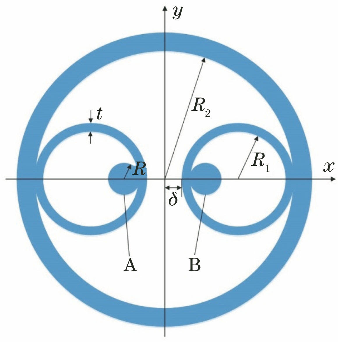
Fig. 1. Cross section diagram of double suspended core THz fiber directional coupler
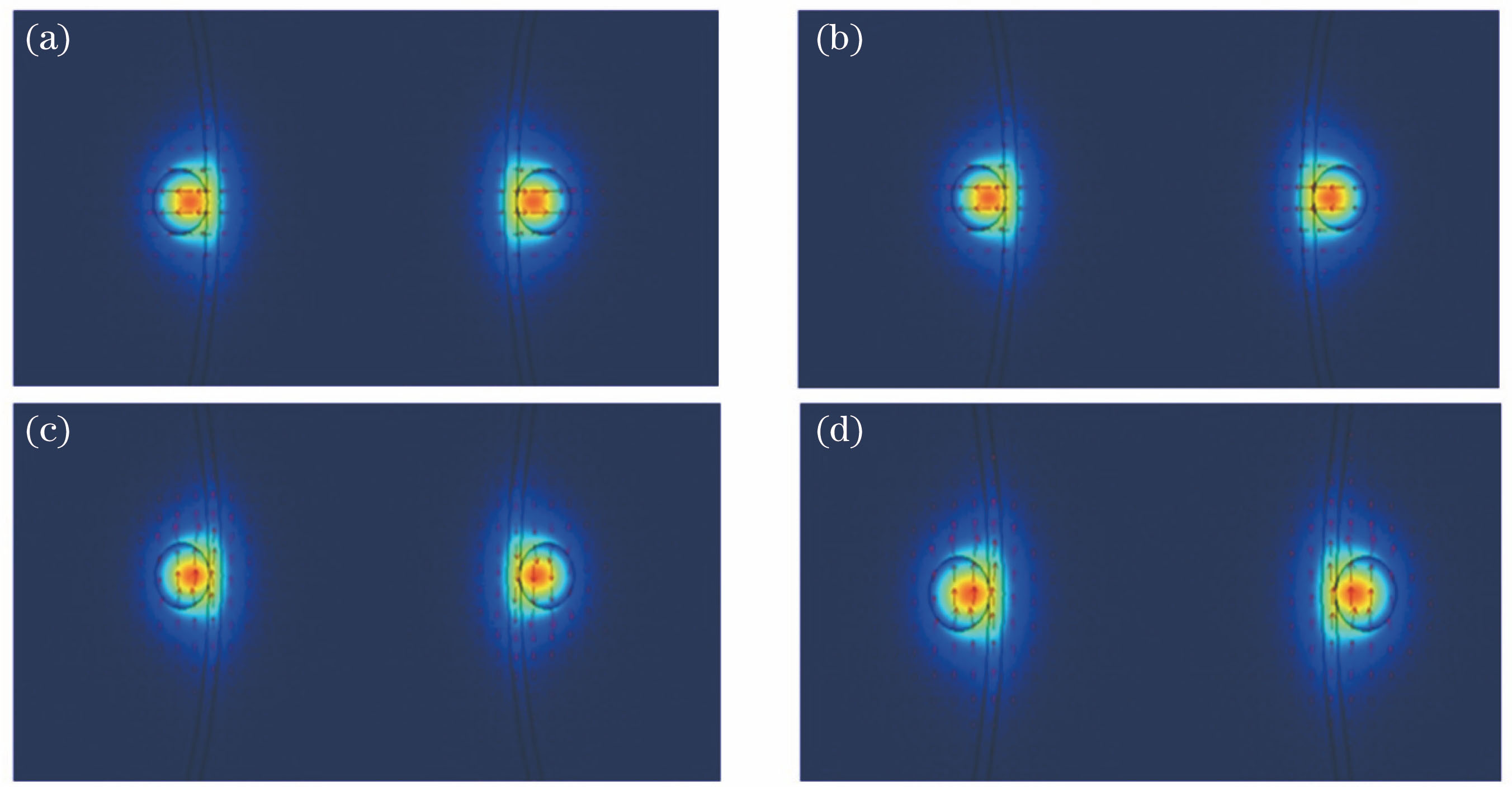
Fig. 2. Mode field distributions of four supermodes. (a) x-polarization odd supermode; (b) x-polarization even supermode; (c) y-polarization odd supermode; (d) y-polarization even supermode
Fig. 3. Subwavelength dual-core coupler structure, and coupling length of x and y polarization modes as a function of R. (a) Subwavelength dual-core coupler structure; (b) coupling length of x and y polarization modes as a function of R
Fig. 4. Variation of coupling length with core radius R. (a) R2=3 mm; (b) t=20 μm
Fig. 5. Insertion loss and polarization dependent loss of coupler as functions of frequency when δ=140 μm, t=20 μm, and R2=3 mm. (a) Core A; (b) core B
Fig. 6. Normalized power of core A and core B as a function of transmission distance when δ=140 μm, t=20 μm, and R2=3 mm. (a) Power change curves of x-polarization mode in two cores; (b) power change curves of y-polarization mode in two cores
Fig. 7. Relationship among K, t, and R. (a) Variation of K value with t under different R2; (b) variation of K value with R under different t
Fig. 8. Device loss of x and y polarization modes varies with t and R. (a) Device loss of x and y polarization modes varies with t at different R2; (b) device loss of x and y polarization modes varies with core radius R at t=20 μm
|
Table 1. Lc,
|
Table 2. Lc,

Set citation alerts for the article
Please enter your email address
© Copyright 2018-2021 | Chinese Laser Press. All Rights Reserved 沪ICP备15018463号-20