• Photonics Research
  • Vol. 9, Issue 4, 452 (2021)
Zhenhuan Tian1、2, Qiang Li1、2, Xuzheng Wang1、2, Mingyin Zhang1、2, Xilin Su1、2, Ye Zhang1、2, Yufeng Li1、2, Feng Yun1、2、*, and S. W. Ricky Lee3、4
Author Affiliations
  • 1Shaanxi Provincial Key Laboratory of Photonics & Information Technology, Xi’an Jiaotong University, Xi’an 710049, China
  • 2Solid-State Lighting Engineering Research Center, Xi’an Jiaotong University, Xi’an 710049, China
  • 3Department of Mechanical and Aerospace Engineering, The Hong Kong University of Science and Technology, Clear Water Bay, Kowloon, Hong Kong, China
  • 4HKUST LED-FPD Technology R&D Center at Foshan, Foshan 528200, China
  • show less
    DOI: 10.1364/PRJ.413069 Cite this Article Set citation alerts
    Zhenhuan Tian, Qiang Li, Xuzheng Wang, Mingyin Zhang, Xilin Su, Ye Zhang, Yufeng Li, Feng Yun, S. W. Ricky Lee. Phosphor-free microLEDs with ultrafast and broadband features for visible light communications[J]. Photonics Research, 2021, 9(4): 452 Copy Citation Text show less
    Schematic illustrations of the fabrication process flow and lateral overgrowth for asymmetric pyramids.
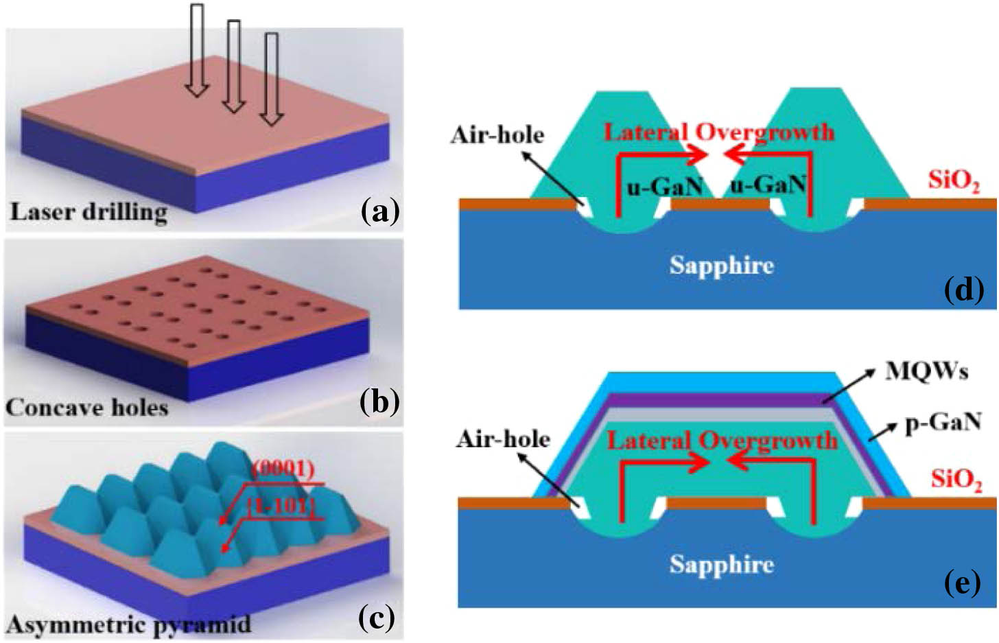
    Fig. 1. Schematic illustrations of the fabrication process flow and lateral overgrowth for asymmetric pyramids.
    (a) Optical images emitted by 405 nm laser and filtered by 450 nm filter; (b) PL intensity of samples 1, 2, 3, and 4; and (c) wavelength distribution for sample 2.
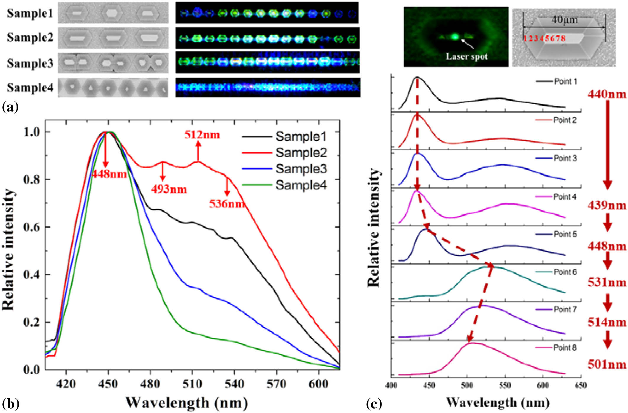
    Fig. 2. (a) Optical images emitted by 405 nm laser and filtered by 450 nm filter; (b) PL intensity of samples 1, 2, 3, and 4; and (c) wavelength distribution for sample 2.
    Cross-section HAADF-STEM images of the point (a) at the semipolar facet, (b) at the edge of (0001) polar facet, (c) at the central part of (0001) facet, and (d) the area in between. The insert image (e) is the SEM image of the cross-section.
    Fig. 3. Cross-section HAADF-STEM images of the point (a) at the semipolar facet, (b) at the edge of (0001) polar facet, (c) at the central part of (0001) facet, and (d) the area in between. The insert image (e) is the SEM image of the cross-section.
    Temporal decay maps of (a) planar LEDs, (b) a single pyramid, and (c) an asymmetric pyramid. TRPL decay curves measured at room temperature for (d) different samples at the main emission wavelength and (e) an asymmetric pyramid with several characteristic peaks.
    Fig. 4. Temporal decay maps of (a) planar LEDs, (b) a single pyramid, and (c) an asymmetric pyramid. TRPL decay curves measured at room temperature for (d) different samples at the main emission wavelength and (e) an asymmetric pyramid with several characteristic peaks.
    Raman spectra recorded on the lateral overgrowth (LO) window, wing, and edge region, accompanied by a planar LED as a reference. The inset displays the recording of the spectra.
    Fig. 5. Raman spectra recorded on the lateral overgrowth (LO) window, wing, and edge region, accompanied by a planar LED as a reference. The inset displays the recording of the spectra.
    Calculated energy band diagrams (a) at equilibrium and (b) under forward bias. (c) Electron and hole wave functions and (d) the radiative recombination rate of LO asymmetric pyramid and planar LED.
    Fig. 6. Calculated energy band diagrams (a) at equilibrium and (b) under forward bias. (c) Electron and hole wave functions and (d) the radiative recombination rate of LO asymmetric pyramid and planar LED.
    Sample Nameτinitial (ns)τfinal (ns)τr (ns)τnr (ns)τ (ns)f3dBpoint_i (MHz)
    Single–4430.56192.441.13384.881.13611.10
    Planar–45418.2694.6145.26189.2136.5218.87
    Point 4–4400.92299.161.85598.331.85373.28
    Point 5–4672.3261.874.82123.744.64148.41
    Point 6–5371.8270.383.73140.753.64189.46
    Point 7–5141.12126.772.26253.542.24307.47
    Point 8–4930.90209.061.80418.121.79384.72
    Table 1. Decay Parameters for Single Pyramid, Planar LEDs, and Asymmetric Pyramid
    Sample NameRaman Shift (cm1)Frequency Shift Δω (cm1)Strain ε (%)αbasal (Å)xPInGaNpz(C/m2)PInGaNsp(C/m2)PGaNsp(C/m2)FInGaN(MV/cm)
    ELO window–Point 6568.00.77−0.323.1880.230.0349−0.0291−0.0344.16
    ELO wing–Point 7567.40.22−0.093.1950.220.0299−0.0292−0.0343.63
    ELO edge–Point 8567.50.33−0.143.1940.210.0353−0.0294−0.0343.51
    Reference570.33.09−1.283.1560.180.0444−0.0298−0.0345.07
    Table 2. Calculated Residual Stress, Polarization Field, and Built-in Electric Field Based on Raman Results
    Zhenhuan Tian, Qiang Li, Xuzheng Wang, Mingyin Zhang, Xilin Su, Ye Zhang, Yufeng Li, Feng Yun, S. W. Ricky Lee. Phosphor-free microLEDs with ultrafast and broadband features for visible light communications[J]. Photonics Research, 2021, 9(4): 452
    Download Citation