
Zixin Zhao, Yiying Zhuang, Zhaoxian Xiao, Hangying Zhang, Chen Fan, Hehui Geng, Hong Zhao, "Characterizing a liquid crystal spatial light modulator at oblique incidence angles using the self-interference method," Chin. Opt. Lett. 16, 090701 (2018)
- Chinese Optics Letters
- Vol. 16, Issue 9, 090701 (2018)
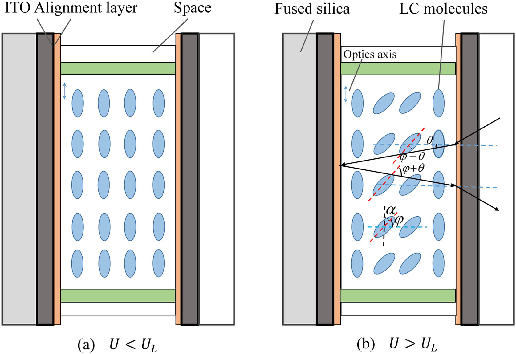
Fig. 1. Schematic diagram of LC-SLM. ITO, indium tin oxide.
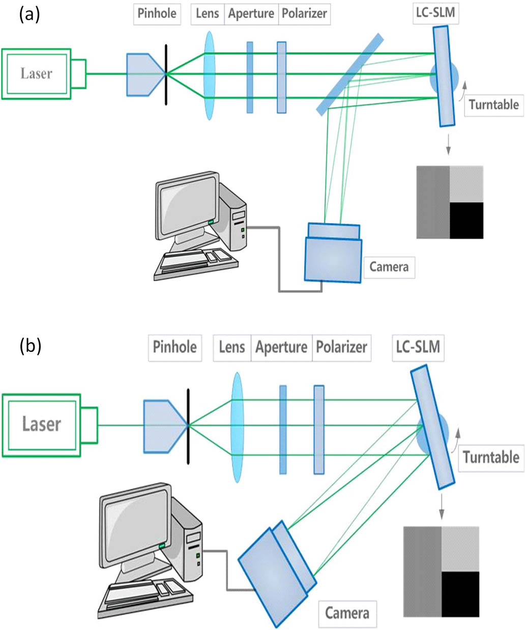
Fig. 2. Self-interference measurement system of LC-SLM under oblique incidence with (a) small incident angle and (b) large incident angle.
Fig. 3. Combined grayscale pattern loaded on the LC-SLM.
Fig. 4. Experimental results: (a) original fringe pattern, (b) extracted fringe pattern by red rectangle, (c) FFT result of one row.
Fig. 5. Comparisons of our proposed method with Fuentes’ method using data from eight experiments. (a) The four phase modulation curves were obtained using Fuentes’ method; (b) the four curves were obtained using our proposed method; (c) the maximum phase difference curves of Fuentes’ method (black squares) and our proposed method (red circles).
Fig. 6. Phase modulation properties of LC-SLM at small incident angles: (a) phase modulation curves for oblique illumination angles of 0°, 1°, 2°, 3°, 4°, 5°; (b) phase modulation values for specific gray levels (0, 48, 96, 152, 200, 255) under different incident angles.
Fig. 7. Phase modulation properties of LC-SLM at large incident angles: (a) phase modulation curves for oblique illumination angles of 0°, 10°, 20°, 30°, 40°, 45°; (b) phase modulation values for specific gray levels (0, 48, 96, 152, 200, 224, 240, 255) under different incident angles.


Set citation alerts for the article
Please enter your email address

© Copyright 2018-2021 | Chinese Laser Press. All Rights Reserved 沪ICP备15018463号-20