
Xiang Chen, Xiongwei Hu, Jinyan Li. Influence Factors of Confinement Loss of Negative Curvature Hollow Core Fiber[J]. Laser & Optoelectronics Progress, 2019, 56(5): 050602
- Laser & Optoelectronics Progress
- Vol. 56, Issue 5, 050602 (2019)
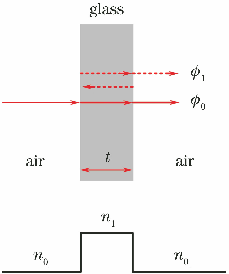
Fig. 1. Schematic of resonance and anti-resonance
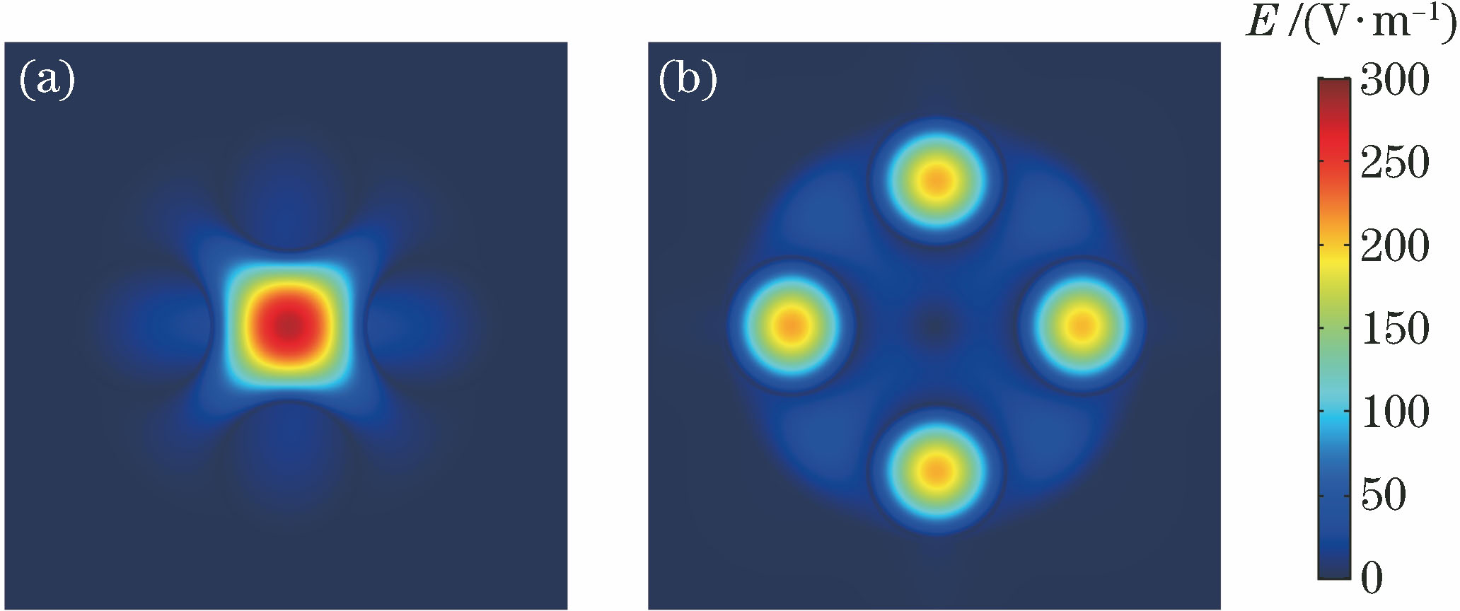
Fig. 2. Electric field mode in negative curvature hollow core fiber. (a) Fundamental mode; (b) tube mode
Fig. 3. Structure of single layer four tubes negative curvature hollow core fiber
Fig. 4. Effective refractive index of fundamental mode at different tube thicknesses
Fig. 5. Power ratio of fundamental mode at different tube thicknesses
Fig. 6. Confinement loss of fundamental mode at different tube thicknesses
Fig. 7. Effective refractive index of fundamental mode and tube mode in single layer four tubes negative curvature hollow core fiber
Fig. 8. Power ratio of fundamental mode in single layer four tubes negative curvature hollow core fiber
Fig. 9. Confinement loss of fundamental mode in single layer four tubes negative curvature hollow core fiber
Fig. 10. Confinement loss of fundamental mode at different tube diameters with 20 μm core diameter
Fig. 11. Confinement loss of fundamental mode at different RT/C
Fig. 12. Negative curvature hollow core fibers. (a) Two layers four tubes with nested tubes; (b) three layers four tubes with nested tubes
Fig. 13. Confinement loss of fundamental mode in two layers four tubes negative curvature hollow core fiber with nested tubes
Fig. 14. Power ratio of fundamental mode in two layers four tubes negative curvature hollow core fiber with nested tubes
Fig. 15. Variation of power ratio of fundamental mode with thickness of air layer in two layers four tubes negative curvature hollow core fiber with nested tubes
Fig. 16. Three layers slab optical waveguide
Fig. 17. Confinement loss of fundamental mode in single layer,two layers and three layers four tubes negative curvature hollow core fibers
Fig. 18. Power ratio of fundamental mode in negative curvature hollow core fibers
Fig. 19. Variation of confinement loss of fundamental mode with thickness of air layer in three layers four tubes negative curvature hollow core fiber with nested tubes
Fig. 20. Confinement loss of fundamental mode in single layer, two layers and, three layers 6 and 8 tubes negative curvature hollow core fibers
|
Table 1. Mode effective index and confinement loss of negative curvature hollow core fiber
|
Table 2. Structural fault tolerance of negative curvature hollow core fiber

Set citation alerts for the article
Please enter your email address
© Copyright 2018-2021 | Chinese Laser Press. All Rights Reserved 沪ICP备15018463号-20