• Chinese Journal of Lasers
  • Vol. 51, Issue 16, 1602101 (2024)
Caiwang Tan1、2、*, Shijia Wang1, Jianhui Su1、2, Xiaohui Han3, Bo Chen1、2, and Xiaoguo Song1、2
Author Affiliations
  • 1Shandong Provincial Key Laboratory of Special Welding Technology, School of Materials Science and Engineering, Harbin Institute of Technology (Weihai), Weihai 264209, Shandong, China
  • 2State Key Laboratory of Advanced Welding and Joining, Harbin Institute of Technology, Harbin 150001, Heilongjiang, China
  • 3CRRC Qingdao Sifang Co., LTD., Qingdao 266111, Shandong, China
  • show less
    DOI: 10.3788/CJL231128 Cite this Article Set citation alerts
    Caiwang Tan, Shijia Wang, Jianhui Su, Xiaohui Han, Bo Chen, Xiaoguo Song. Single Side Resistance Spot Welding Process and Performance of Stainless Steel and Glass Fiber Reinforced Plastics Based on Laser Texturing[J]. Chinese Journal of Lasers, 2024, 51(16): 1602101 Copy Citation Text show less
    Schematic of micro-texture preparation by nanosecond laser
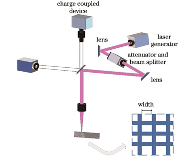
    Fig. 1. Schematic of micro-texture preparation by nanosecond laser
    Schematic of single-side resistance spot welding
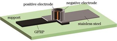
    Fig. 2. Schematic of single-side resistance spot welding
    Schematic of tensile-shear testing on SUS304/GFRP joint by single-side resistance spot welding
    Fig. 3. Schematic of tensile-shear testing on SUS304/GFRP joint by single-side resistance spot welding
    3D morphologies of micro-textures with different widths on stainless surface. (a) Untreated; (b) 0.1 mm; (c) 0.2 mm; (d) 0.3 mm; (e) 0.4 mm; (f) 0.5 mm
    Fig. 4. 3D morphologies of micro-textures with different widths on stainless surface. (a) Untreated; (b) 0.1 mm; (c) 0.2 mm; (d) 0.3 mm; (e) 0.4 mm; (f) 0.5 mm
    Contact angles of molten GFRPs on SUS304 surfaces with different micro-texture widths
    Fig. 5. Contact angles of molten GFRPs on SUS304 surfaces with different micro-texture widths
    Macroscopic morphologies of typical stainless steel /GFRP joint. (a) Front surface; (b) back surface
    Fig. 6. Macroscopic morphologies of typical stainless steel /GFRP joint. (a) Front surface; (b) back surface
    Optical morphologies of typical stainless steel/GFRP joints at interface under different micro-texture widths. (a) Untreated; (b) 0.1 mm; (c) 0.2 mm; (d) 0.3 mm; (e) 0.4 mm; (f) 0.5 mm
    Fig. 7. Optical morphologies of typical stainless steel/GFRP joints at interface under different micro-texture widths. (a) Untreated; (b) 0.1 mm; (c) 0.2 mm; (d) 0.3 mm; (e) 0.4 mm; (f) 0.5 mm
    SEM morphologies of interfaces of typical stainless steel/GFRP joints with different micro-texture widths. (a) 0.1 mm; (b) 0.2 mm; (c) 0.3 mm; (d) 0.4 mm; (e) 0.5 mm
    Fig. 8. SEM morphologies of interfaces of typical stainless steel/GFRP joints with different micro-texture widths. (a) 0.1 mm; (b) 0.2 mm; (c) 0.3 mm; (d) 0.4 mm; (e) 0.5 mm
    Elements distributions of interfaces of typical stainless steel/GFRP joints along different paths. (a) Line 1; (b) line 2; (c) line 3; (d) line 4
    Fig. 9. Elements distributions of interfaces of typical stainless steel/GFRP joints along different paths. (a) Line 1; (b) line 2; (c) line 3; (d) line 4
    Tensile-shear force values of stainless steel/GFRP joints with different micro-texture widths
    Fig. 10. Tensile-shear force values of stainless steel/GFRP joints with different micro-texture widths
    3D fracture images of SUS304/GFRP joints
    Fig. 11. 3D fracture images of SUS304/GFRP joints
    Fracture morphologies of typical stainless steel/GFRP joints. (a1)‒(a3) Fracture at GFRP side without micro-texture; (b1)‒(b3) fracture at stainless steel side without micro-texture; (c1)‒(c3) fracture at stainless steel side with micro-texture; (d1)‒(d3) fracture at GFRP side with micro-texture
    Fig. 12. Fracture morphologies of typical stainless steel/GFRP joints. (a1)‒(a3) Fracture at GFRP side without micro-texture; (b1)‒(b3) fracture at stainless steel side without micro-texture; (c1)‒(c3) fracture at stainless steel side with micro-texture; (d1)‒(d3) fracture at GFRP side with micro-texture
    Mechanism of single-side resistance spot welding of stainless steel/GFRP under micro-texture control. (a) Macroscopic heat conduction joining; (b) untreated; (c) micro-texture width is suitable; (d) micro-texture width is wide or narrow
    Fig. 13. Mechanism of single-side resistance spot welding of stainless steel/GFRP under micro-texture control. (a) Macroscopic heat conduction joining; (b) untreated; (c) micro-texture width is suitable; (d) micro-texture width is wide or narrow
    ElementCMnSiCrNiSFe
    Mass fraction /%0.031.500.7518.00‒20.008.00‒10.000.02Bal.
    Table 1. Chemical compositions of 304 stainless steel
    Process parameterValue
    Laser power /W80
    Scanning speed /(mm·s-11000
    Defocus distance /mm0
    Width of micro-texture /mm0.1, 0.2, 0.3, 0.4, 0.5
    Table 2. Process parameters of laser texturing platform
    Process parameterValue
    Welding current /A2600
    Welding time /s1.0
    Electrode pressure /MPa0.3
    Negative electrode outer diameter /mm20
    Negative electrode inner diameter /mm16
    Positive electrode diameter /mm10
    Table 3. Process parameters of single-side resistance spot welding
    Caiwang Tan, Shijia Wang, Jianhui Su, Xiaohui Han, Bo Chen, Xiaoguo Song. Single Side Resistance Spot Welding Process and Performance of Stainless Steel and Glass Fiber Reinforced Plastics Based on Laser Texturing[J]. Chinese Journal of Lasers, 2024, 51(16): 1602101
    Download Citation