Abstract
Smith–Purcell radiation (SPR) is the electromagnetic wave generated by free electrons passing above a diffraction grating, and it has played an important role in free-electron light sources and particle accelerators. Orbital angular momentum (OAM) is a new degree of freedom that can significantly promote the capacity of information carried by an electro-magnetic beam. In this paper, we propose an integrable method for generating vortex Smith–Purcell radiation (VSPR), namely, SPR carrying OAM, by having free-electron bunches pass on planar holographic gratings. VSPRs generated by different electron energies, with different topological charges of the OAM, radiation angles, and frequencies are demonstrated numerically. It is also found that, for high-order radiation, the topological charge of the OAM wave will be multiplied by the radiation order. This work introduces a new way to generate SPR with OAM and provides a method to achieve an integratable and tunable free-electron OAM wave source at different frequency regions.1. INTRODUCTION
An electron moving close to the surface of a diffraction grating would radiate an electromagnetic (EM) wave, which was discovered by S. J. Smith and E. M. Purcell and named Smith–Purcell radiation (SPR) [1]. According to the Huygens construction, the radiation wavelength is determined by , where is the period of the grating, is the velocity of the electron, is the radiation order (), is light speed in vacuum, and is the radiation angle [1]. The SPR could also be understood according to dipole radiation theory and evanescent-wave scattering theory [2,3]. In the past 60 years, SPR has been widely investigated both theoretically and experimentally, giving rise to applications in the field of free-electron light sources and particle accelerators [4–24].
By manipulating the free electrons and the structure interacting with the electrons, the characteristics of SPR, including radiation wavelength, intensity, and polarization, can be controlled. When the electrons are bunched to a scale much smaller than the radiated wavelength, the intensity of SPR will be proportional to the square of the bunch charges, which is known as coherent SPR [10]. A train of periodic electron bunches could cause superradiant SPR, which is not only coherent but also radiated to a certain direction with super-narrow spectrum [11,13]. Based on Al grating with a nano-slot, the gap between the electrons and the grating is controlled within about 10 nm, leading to an extension of the wavelength of SPR to the deep-ultraviolet region [23]. By using complex periodic and aperiodic gratings, researchers developed a systematic method to shape the angular and spectral distributions of SPR [20]. Recently, it was reported that the polarization of SPR could be well manipulated using Babinet metasurfaces consisting of periodically distributed C-aperture resonators or antennas [17,18].
Distinct from the angular momentum due to the polarization states, orbital angular momentum (OAM) was first proposed by Allen [25] in 1992. An EM wave with OAM (vortex EM wave) has a helical equiphase surface and is expressed by a divisor , where is the azimuthal coordinate and is the topological charge (TC). Due to its potential for being applied in many fields [26–28], the vortex beam has attracted great attention. Various methods have been used to generate vortex beams in different wave ranges, like spiral phase plates [29], metamaterials [30], V-shape antennas [31], and ring waveguides [32]. Recently, relativistic electron beam excited coherent OAM waves were demonstrated using two undulators [33]. The surface plasmon polaritons carrying OAM were studied numerically by having free electrons rotate around the nanowire using an extremely intense magnetic field [34]. SPR with spiral field and a TC of 1 (or ) was generated from a three-dimensional helical metagrating in microwave region [24]. However, based on the above methods, the devices are hard to be minimized or integrated, since the extremely intense magnetic field or three-dimensional grating was adopted.
Sign up for Photonics Research TOC. Get the latest issue of Photonics Research delivered right to you!Sign up now
In this paper, we propose an integrable method to flexibly generate vortex Smith–Purcell radiation (VSPR), namely, SPR that carries OAM, by having free electrons interact with a planar holographic grating. The simulation results indicate that coherent OAM wave with different TCs and in different frequency regions, including the ultraviolet, visible light, infrared, terahertz (THz), and microwave regions, could be derived by designing different holographic gratings. It is also found that the radiation angle of the OAM wave could be tuned easily, and the TC would be multiplied when high-order SPR is generated. This work introduces a new way to manipulate the OAM of free-electron-induced radiation and to develop an integrable and tunable vortex wave source in different frequency regions.
2. RESULTS AND DISCUSSION
Figure 1 shows the schematic of generating an OAM wave by having periodic free-electron bunches pass over a holographic grating. The holographic grating has a similar configuration to a traditional grating, except for the fork structure. The teeth number in the fork structure is equal to the TC () of OAM plus 1. The holographic grating structure is obtained by assuming the interference between the anticipated OAM wave (Laguerre–Gaussian beam) propagating against the direction (referred to as object light) and an evanescent wave propagating along the axis (referred to as reference light) [25]. According to the theory that SPR is caused by the scattering of the evanescent wave around the free electrons and the holographic theory [3,35], when periodic electron bunches pass on the holographic grating with the same velocity as the phase velocity of reference wave, the evanescent wave around the electron bunch will play the role of the reference wave and be diffracted into an OAM wave propagating along the axis, resulting in a superradiant VSPR.
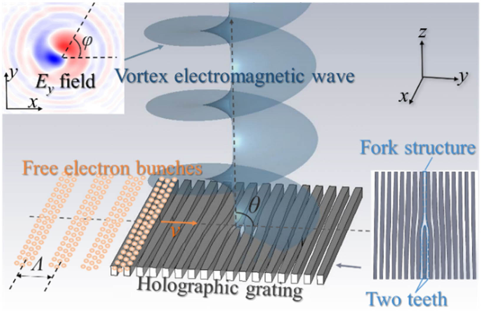
Figure 1.Schematic diagram of generating vortex Smith–Purcell radiation (with a TC of for example) with free-electron bunches and holographic grating. The free electrons are periodically bunched in the direction with pitch much smaller than the radiating wavelength. The velocity of the electron bunches is . The holographic grating (top view is shown in the inset) is made of metal or dielectrics depending on the frequency of VSPR and has a fork structure with two teeth. When periodic free-electron bunches pass on the holographic grating, an orbital angular momentum (OAM) wave would be emitted at an angle with respect to the axis.
Here the particle-in-cell finite-difference time-domain (PIC-FDTD) algorithm is applied for simulation. To clearly demonstrate the process of generating the OAM wave, we take THz frequency as an example in most discussions, and the simulation results in other frequency regions are also presented in the latter part of this paper. For generating a THz OAM wave, the holographic grating of perfect electric conductor (PEC) at THz frequency is designed. At the frequency of 1 THz, the SPR generated with periodic grating is shown in Fig. 2(a), which can be regarded as an OAM wave with a TC of . The interference of the OAM wave with a TC of and the reference wave with ( is the wavevector along the flying direction of free electrons and is the wavevector in vacuum) results in the structure of holographic grating shown in the left figure in Fig. 2(b). The holographic grating with a fork structure in the center has an area of , a thickness of 60 μm, and an approximate period () of 100 μm ( equals the wavelength of the reference wave in the hologram calculation). In the simulation, a train of periodically bunched sheet-current free electrons with a velocity of , bunching frequency of , bunch charge of , and a bunch length of (much smaller than the radiation wavelength 300 μm), is launched above the holographic grating. The middle and right figures in Fig. 2(b) show that an OAM wave with at frequency of 1 THz and radiation angle of has been obtained, respectively.

Figure 2.Simulation of a THz OAM wave with TCs of (a) 0 (traditional SPR from periodic grating), (b) 1, (c) 2, (d) 3, (e) 4, and (f) 10. Left: Top view of the gratings (gray part represents PEC, white part represents vacuum), in which the teeth of the fork structures are marked. Middle: Side view of the field ( in the plane, the observation planes are shown as red-dashed lines in the right colomn) of the OAM wave with different TCs. The radiation angle is about 90°, and the vortex wave propagates along the direction. Right: Top view (the observation planes are shown as green-dashed lines in the middle column) of the field above the grating, which clearly shows the vortex shape and the phase change of (, and 10) with varying .
By varying the TC () of the OAM wave used in the hologram calculation, we can design the holographic grating for generating an OAM wave with larger TCs. As shown in Figs. 2(c)–2(f), using holographic gratings with more teeth, OAM waves with , and 10 are obtained when excited by the free-electron bunches mentioned above. From (the main component of the radiated electric field) field in the observation plane (middle column of Fig. 2), we can confirm the stagger of the equiphase surface in the side view. The field in the observation plane perpendicular to the direction above the grating (right column of Fig. 2) clearly shows the vortex shape and the phase change of (, and 10) with varying . The mode purities (ratio of intensity of the expected OAM mode to that of the whole beam) of the radiated beams shown in Figs. 2(b)–2(f) are estimated as 0.87, 0.84, 0.81, 0.80, and 0.69, respectively, which decrease with larger because of the finite calculating range in the simulation. Figure 2(f) indicates that OAM wave with a large could be obtained, while the area of the holographic grating should be enlarged sufficiently to improve the mode purity. For generating OAM with negative , we should only apply a mirror reversal (along the direction) of the holographic grating to generate an OAM wave with a positive TC.
VSPR mixed with an OAM mode can also be generated based on our proposed method. Using mixed OAM waves ( and with intensity ratio of 0.5:0.5) in the hologram calculation, the holographic grating could be derived and shown in Fig. 3(a), which has two fork profiles as its feature structure. With other simulation settings the same as those of Fig. 2(b), except the enlarged area of , the radiated VSPR is shown in Figs. 3(b) and 3(c). According to the mode shown in Fig. 3(c) and the standard Laguerre–Gaussian mode, the OAM spectrum of the radiated beam is calculated and shown in Fig. 3(d), in which the normalized intensity is estimated as 0.40 and 0.41 for the modes with and , respectively. Here, although we only show two OAM waves mixed with VSPR, it is anticipated that VSPR mixed with more OAM waves with different intensity ratios and fractional [36] VSPR could be generated.
Figure 3.Simulation of THz VSPR with mixed mode of and (ratio of intensity: 0.5:0.5). (a) The holographic grating used in this simulation; (b) side view of the radiation field ( in the plane); (c) top view of the radiation field ( in the plane). The observation plane is 10 mm away from the holographic grating. (d) Normalized OAM spectrum of the radiated beam, in which the intensity is 0.40 for the mode and 0.41 for the mode.
As we know, the velocity of free electrons for generating SPR could be greatly reduced by decreasing the pitch of the grating [1,3]. Here VSPR can also be generated by low-energy free electrons by decreasing the period and scale of the holographic grating. For example, with an OAM wave having and a reference wave having and in the hologram calculation, the holographic grating could be obtained as shown in Figs. 4(b) and 4(c), which have similar structure but decreased size compared with that in Fig. 4(a) [the same as that in Fig. 2(b)]. Then, excited by free electrons with lower velocities of (kinetic energy ) and (), OAM waves with are generated and shown in Figs. 4(b) and 4(c) (side view in the middle column and top view in the right column).
Figure 4.OAM wave at with generated by electrons with velocity of (a) (), (b) (), (c) (). Left: The holographic grating for different electron velocities. Middle: Side view of the radiated field (the observation planes are shown as the red-dashed lines in the right colomn). The green rectangles circle the holographic gratings. Right: Top view of the radiated field. The observation planes for the right figures are perpendicular to the axis (shown as the green-dashed lines in the middle colomn). The field is normalized individually in each figure.
Here the calculated radiation power of an OAM wave for Fig. 4(a) is about 180 nW when the charge of the free-electron bunch is . This value is in the same order of that generated by a conventional grating with pitch of 100 μm as well as the same simulation settings of the free electrons and PEC material. The reason can be understood as follows. Ignoring the fork structure, the holographic grating is similar to a conventional grating with pitch . Although the fork structure in holographic grating results in the deviation of pitch from and the radiation power difference, the fork structure just has a small area in the whole holographic grating, which would result in the close radiation efficiency of holographic grating and conventional grating. However, in numerical simulation, the mesh also has a nonnegligible influence on the radiation power, so the exact value of radiation power difference cannot be known.
The radiation power for Figs. 4(b) and 4(c) is estimated by simulation as 145 nW and 87 nW, respectively, while the bunch charge and bunching frequency are fixed as and . According to the above analysis, the radiation efficiency of VSPR should follow the basic rule of conventional SPR. Although here lower electron energy corresponds to lower radiation power, there should exist an optimized electron energy to derive the largest radiation power [16,37]. According to results of low-energy electron excited VSPR, we suggest good prospect for achieving a highly integrated OAM wave emitter based on the low-energy electrons and planar holographic grating.
According to the formula , the radiation angle is related to the radiation frequency [1,3]. Here it is found that this formula also works for OAM wave generation based on the holographic grating. Taking an OAM wave with as an example, the bunching frequency of the sheet-current electrons in simulation is varied to control the wavelength and radiation angle of the OAM wave. For the holographic grating in Fig. 2(c), varying the bunching frequencies of free electrons at 0.68, 0.6, and 0.43 THz (fixing and ), Fig. 5 illustrates that the frequency (wavelength) of the radiated OAM wave becomes 1.36 THz (220 μm), 1.2 THz (250 μm), and 0.86 THz (350 μm), respectively. The corresponding radiation angles are 37°, 60°, and 120°, respectively, which can be seen clearly from the left column of Fig. 5. The right column in Fig. 5 shows the field in the observation plane perpendicular to the radiating direction. The radiation frequency and angle are in good agreement with the above formula. Thus, by controlling the free-electron bunches, the frequency and radiation direction of the OAM wave can be tuned flexibly.
Figure 5.OAM wave generated by free electrons with bunching frequency of (a) 0.68 THz, (b) 0.6 THz, and (c) 0.43 THz. Left, field in the plane. Right, field of the OAM wave in the observation plane perpendicular to the propagating direction (corresponding to the green dashed line). The corresponding radiation frequency (wavelength) is 1.36 THz (220 μm), 1.2 THz (250 μm), and 0.86 THz (350 μm), which follows the formula raised by Smith and Purcell. The parameters of the holographic grating are the same as those of Fig. 2(c), and the free-electron velocity is .
An interesting phenomenon of SPR with OAM generated by holographic grating is that the TC () of a higher-harmonic OAM wave () has the TC () of the fundamental mode multiplied by , namely, . This can be understood by reviewing how SPR is obtained according to the Huygens principle. As shown in Fig. 6(a), a train of free-electron bunches passing on a conventional grating generates a series of wavelets, and the superposition of wavelets forms the equiphase surface of SPR. For certain period and velocity of the free-electron bunches, the radiation angle is . The corresponding three-dimensional schematic figures are also shown in Fig. 6(a). Compared with the first-order SPR (), the second-order SPR () has half the distance between the two equiphase surfaces with phase difference and thus a doubled radiation frequency. When the conventional grating is replaced by a holographic grating, the spatial distribution of the holographic grating causes a phase distribution in the plane. As illustrated in Fig. 6(b), the holographic grating with a two-teeth fork structure generates the distorted equiphase surfaces of fundamental OAM wave [, left of Fig. 6(b)], which has ( is the label of the holographic grating [38], which equals the TC of the OAM wave used for designing holographic grating). For the second-order mode (), the equiphase surfaces are shown in the right figure of Fig. 6(b), which would result in a phase change of when we have vary . Thus, the TC of the second OAM wave is . Since the ratio of the speed of the electrons to that of the radiated wave is a constant for different , the screw pitch of the helical equiphase would not change with the radiation order according to Huygens principle, so we have . Further, it is easy to deduce that the TC of the th-order mode is , according to the feature of the helical equiphase surface. The OAM waves illustrated in Fig. 2 are the fundamental mode (namely, ) with different TCs at a frequency of 1 THz. Setting the monitor in simulation at frequency of 2 THz, the second-order mode () could be found as shown in Fig. 6(c). Compared with the fundamental mode, the second-harmonic OAM wave at frequency of 2 THz has a doubled TC and weaker radiation intensity. Based on this feature, an OAM wave with a large TC could be generated with a simple holographic grating structure.
Figure 6.(a) Schematic of the Huygens construction for conventional SPR with a radiation angle of . A train of free-electron bunches passes above a conventional grating. The red and black dashed arc lines represent the wave fronts of the wavelets generated by the electrons in respective color, while the gray ones show the equiphase surfaces of the wavelets corresponding to second-order SPR, which has () phase delay compared with the wave front. The blue and orange lines show the equiphase surfaces of the SPR. Three-dimensional schematics of the equiphase surfaces of the conventional SPR are shown below. The distances between each two adjacent equiphase surfaces (namely, wavelength) are and for the first- and second-order SPR, respectively. (b) Schematic of the equiphase surface of the first- and second-order OAM generated by holographic grating. (c) Second-harmonic OAM wave at frequency of 2 THz. The holographic gratings shown in the inset are the same as those illustrated in the left figures of Fig. 2. The TC of second-harmonic OAM wave is doubled compared with that of fundamental mode.
Besides the THz band, this OAM wave generation method could be applied in a wide frequency range, including the microwave, infrared, visible, and ultraviolet bands. For different frequency regions, the parameters of the holographic grating and the free-electron bunches are listed in Table 1. For the infrared (164 THz), visible (500 THz), and ultraviolet (1640 THz) frequency regions, the materials used for holographic grating are selected as silicon (Si, ) [39], gold (Au, using the Drude model [40]), and aluminum (Al, using the Drude model [40]), respectively, and the sizes of the holographic grating are much smaller than those used in the microwave/THz frequency region. The holographic gratings are designed for fundamental OAM waves with a TC of . Figure 7 illustrates the generated OAM wave with based on the corresponding holographic grating. Thus, it can be seen that VSPR, which provides a new method to generate OAM waves, is available for a wide range of frequencies.
| | Parameters of Holographic Gratings | Parameters of Free-Electron Bunch |
| Frequency | Wavelength | Material/Permittivity | Thickness | Period (d) | Area | Velocity | Bunching Frequency |
| 16.4 GHz | 18.3 mm | PEC | 3.6 mm | 6.1 mm | | | 8.2 GHz |
| 1 THz | 300 μm | PEC | 60 μm | 100 μm | | | 0.5 THz |
| 164 THz | 1.83 μm | [39] | 360 nm | 610 nm | | | 82 THz |
| 500 THz | 600 nm | Au (Drude model) [40] | 120 nm | 200 nm | | | 250 THz |
| 1640 THz | 183 nm | Al (Drude model) [40] | 36 nm | 61 nm | | | 820 THz |
Table 1. Parameters of the Simulations in Different Frequency Regions
Figure 7.OAM wave generated in different frequency regions. The field plotted in each figure is normalized individually. The holographic gratings for different frequencies have similar profile to the left figure in Fig. 2(d), but the scales of the holographic gratings and material permittivity are different, which are shown in Table 1.
3. CONCLUSION
To summarize, we propose an integrable method to generate SPR carrying OAM by using periodic free-electron bunches passing on a planar holographic grating, and numerical simulation has been carried out. The results reveal that OAM waves with different TCs (, and 10) are derived by designing fork structures with different teeth numbers in the holographic grating. For different electron velocities (, , ), it is found that by shrinking the size of holographic grating, the velocity (kinetic energy ) of free electrons could be greatly reduced for producing OAM waves with the same frequency and topological charge, which is important for realizing integrated VSPR devices. Furthermore, by changing the electrons’ bunching frequency, the wavelength (frequency) of OAM wave can be easily tuned, and the relationship between the wavelength and radiation angle satisfies the formula raised by Smith and Purcell [1]. An interesting phenomenon is found in which a higher-order () OAM wave has a TC of ( is the TC of the first-order mode), which has not been reported before to our knowledge. Finally, it is shown that this OAM wave generation method is available in a wide frequency region, including ultraviolet, visible light, infrared, terahertz wave, and microwave. This work provides a new method to manipulate the OAM of SPR and to realize integrable and tunable vortex wave sources in different frequency regions.
References
[1] S. J. Smith, E. M. Purcell. Visible light from localized surface charges moving across a grating. Phys. Rev., 92, 1069(1953).
[2] D. Francia, G. Toraldo. On the theory of some Čerenkovian effects. Il Nuov. Cim., 16, 61-77(1960).
[3] K. Ishiguro, T. Tako. An estimation of Smith-Purcell effect as the light source in the infra-red region. Opt. Act., 8, 25-31(1961).
[4] P. M. Van den Berg. Smith-Purcell radiation from a line charge moving parallel to a reflection grating. J. Opt. Soc. Am., 63, 689-698(1973).
[5] K. Mizuno, S. Ono, O. Shimoe. Interaction between coherent light waves and free electrons with a reflection grating. Nature, 253, 184-185(1975).
[6] J. M. Wachtel. Free-electron lasers using the Smith-Purcell effect. J. Appl. Phys., 50, 49-56(1979).
[7] A. Gover, P. Dvorkis. Angular radiation pattern of Smith-Purcell radiation. J. Opt. Soc. Am. B, 1, 723-728(1984).
[8] G. Doucas, J. H. Mulvey, M. Omori, J. Walsh, M. F. Kimmitt. First observation of Smith-Purcell radiation from relativistic electrons. Phys. Rev. Lett., 69, 1761-1764(1992).
[9] K. J. Woods, J. E. Walsh, R. E. Stoner, H. G. Kirk, R. C. Fernow. Forward directed Smith-Purcell radiation from relativistic electrons. Phys. Rev. Lett., 74, 3808-3811(1995).
[10] K. Ishi, Y. Shibata, T. Takahashi, S. Hasebe, M. Ikezawa, K. Takami, T. Matsuyama, K. Kobayashi, Y. Fujita. Observation of coherent Smith-Purcell radiation from short-bunched electrons. Phys. Rev. E, 51, R5212-R5215(1995).
[11] J. Urata, M. Goldstein, M. F. Kimmitt, A. Naumov, C. Platt, J. E. Walsh. Superradiant Smith-Purcell emission. Phys. Rev. Lett., 80, 516-519(1998).
[12] H. L. Andrews, C. A. Brau. Gain of a Smith-Purcell free-electron laser. Phys. Rev. ST Accel. Beams, 7, 070701(2004).
[13] S. E. Korbly, A. S. Kesar, J. R. Sirigiri, R. J. Temkin. Observation of frequency-locked coherent terahertz Smith-Purcell radiation. Phys. Rev. Lett., 94, 054803(2005).
[14] G. Adam, K. F. MacDonald, N. I. Zheludev, Y. H. Fu, C. M. Wang, D. P. Tsai, F. J. GarciadeAbajo. Light well: a tunable free-electron light source on a chip. Phys. Rev. Lett., 103, 113901(2009).
[15] J. Gardelle, P. Modin, J. T. Donohue. Start current and gain measurements for a Smith-Purcell free-electron laser. Phys. Rev. Lett., 105, 224801(2010).
[16] Y. Yang, A. Massuda, C. Roques-Carmes, S. E. Kooi, T. Christensen, S. G. Johnson, J. D. Joannopoulos, O. D. Miller, I. Kaminer, M. Soljačić. Maximal spontaneous photon emission and energy loss from free electrons. Nat. Phys., 14, 894-899(2018).
[17] Z. Wang, K. Yao, M. Chen, H. Chen, Y. Liu. Manipulating Smith-Purcell emission with Babinet metasurfaces. Phys. Rev. Lett., 117, 157401(2016).
[18] Y. Yang, C. Roques-Carmes, I. Kaminer, A. Zaidi, A. Massuda, Y. Yang, S. E. Kooi, K. Berggren, S. Marin. Manipulating Smith-Purcell radiation polarization with metasurfaces. CLEO: QELS_Fundamental Science, FW4H.1(2018).
[19] A. Massuda, C. Roques-Carmes, A. Solanki, Y. Yang, S. E. Kooi, F. Habbal, I. Kaminer, S. Marin. High-order Smith-Purcell radiation in silicon nanowires. CLEO: QELS_Fundamental Science, JTh5B.8(2017).
[20] R. Remez, N. Shapira, C. Roques-Carmes, R. Tirole, Y. Yang, Y. Lereah, M. Soljacic, I. Kaminer, A. Arie. Spectral and spatial shaping of Smith-Purcell radiation. Phys. Rev. A, 96, 061801(2017).
[21] A. Massuda, C. Roques-Carmes, Y. Yang, S. E. Kooi, Y. Yang, C. Murdia, K. K. Berggren, I. Kaminer, M. Soljačić. Smith-Purcell radiation from low-energy electrons. ACS Photon., 5, 3513-3518(2018).
[22] J. K. So, F. J. García de Abajo, K. F. MacDonald, N. I. Zheludev. Amplification of the evanescent field of free electrons. ACS Photon., 2, 1236-1240(2015).
[23] Y. Ye, F. Liu, M. Wang, L. Tai, K. Cui, X. Feng, W. Zhang, Y. Huang. Deep-ultraviolet Smith-Purcell radiation. Optica, 6, 592-597(2019).
[24] L. Jing, Z. Wang, X. Lin, B. Zheng, S. Xu, L. Shen, Y. Yang, F. Gao, M. Chen, H. Chen. Spiral field generation in Smith-Purcell radiation by helical metagratings. Research, 2019, 3806132(2019).
[25] L. Allen, M. W. Beijersbergen, R. J. C. Spreeuw, J. P. Woerdman. Orbital angular momentum of light and the transformation of Laguerre-Gaussian laser modes. Phys. Rev. A, 45, 8185-8189(1992).
[26] M. P. J. Lavery, F. C. Speirits, S. M. Barnett, M. J. Padgett. Detection of a spinning object using light’s orbital angular momentum. Science, 341, 537-540(2013).
[27] K. Oyoda, K. Miyamoto, N. Aoki, R. Morita, T. Omatsu. Using optical vortex to control the chirality of twisted metal nanostructures. Nano Lett., 12, 3645-3649(2012).
[28] D. G. Grier. A revolution in optical manipulation. Nature, 424, 810-816(2003).
[29] P. Schemmel, G. Pisano, B. Maffei. Modular spiral phase plate design for orbital angular momentum generation at millimetre wavelengths. Opt. Express, 22, 14712-14726(2014).
[30] M. Kang, J. Chen, B. Gu, Y. Li, L. T. Vuong, H. T. Wang. Spatial splitting of spin states in subwavelength metallic microstructures via partial conversion of spin-to-orbital angular momentum. Phys. Rev. A, 85, 035801(2012).
[31] J. He, X. Wang, D. Hu, J. Ye, S. Feng, Q. Kan, Y. Zhang. Generation and evolution of the terahertz vortex beam. Opt. Express, 21, 20230-20239(2013).
[32] Y. Wang, X. Feng, D. Zhang, P. Zhao, X. Li, K. Cui, F. Liu, Y. Huang. Generating optical superimposed vortex beam with tunable orbital angular momentum using integrated devices. Sci. Rep., 5, 10958(2015).
[33] E. Hemsing, A. Knyazik, M. Dunning, D. Xiang, A. Marinelli, C. Hast, J. B. Rosenzweig. Coherent optical vortices from relativistic electron beams. Nat. Phys., 9, 549-553(2013).
[34] L. Xiao, J. Chen, L. Chen, Q. Zhang, L. Guo, M. Yang. Electron beam excited surface plasmon polaritons carrying orbital angular momentum. 12th International Symposium on Antennas, Propagation and EM Theory (ISAPE), 1-3(2018).
[35] R. Collier. Optical Holography(2013).
[36] J. B. Götte, K. O’Holleran, D. Preece, F. Flossmann, S. Franke-Arnold, S. M. Barnett, M. J. Padgett. Light beams with fractional orbital angular momentum and their vortex structure. Opt. Express, 16, 993-1006(2008).
[37] F. Liu, L. Xiao, Y. Ye, M. Wang, K. Cui, X. Feng, W. Zhang, Y. Huang. Integrated Cherenkov radiation emitter eliminating the electron velocity threshold. Nat. Photonics, 11, 289-292(2017).
[38] A. Nicolas, L. Veissier, E. Giacobino, D. Maxein, J. Laurat. Quantum state tomography of orbital angular momentum photonic qubits via a projection-based technique. New J. Phys., 17, 033037(2015).
[39] H. H. Li. Refractive index of silicon and germanium and its wavelength and temperature derivatives. J. Phys. Chem. Ref. Data, 9, 561-658(1980).
[40] K. H. Lee, I. Ahmed, R. S. M. Goh, E. H. Khoo, E. P. Li, T. G. G. Hung. Implementation of the FDTD method based on Lorentz-Drude dispersive model on GPU for plasmonics applications. Prog. Electromagn. Res., 116, 441-456(2011).

