
Chengmin Lei, Zilun Chen, Yanran Gu, Hu Xiao, Jing Hou, "Loss mechanism of all-fiber cascaded side pumping combiner," High Power Laser Sci. Eng. 6, 04000e56 (2018)
- High Power Laser Science and Engineering
- Vol. 6, Issue 4, 04000e56 (2018)
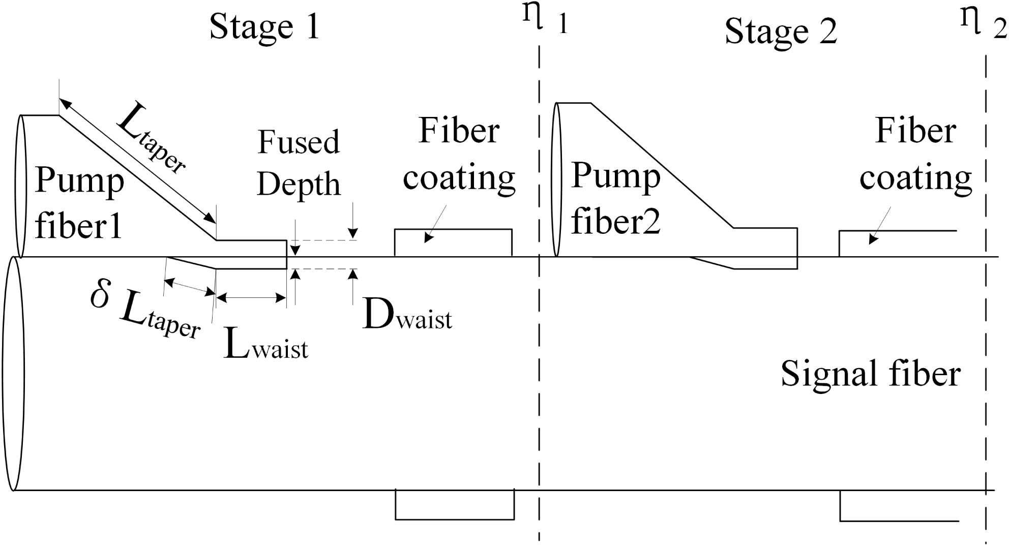
Fig. 1. The longitudinal scheme of the cascaded combiner.
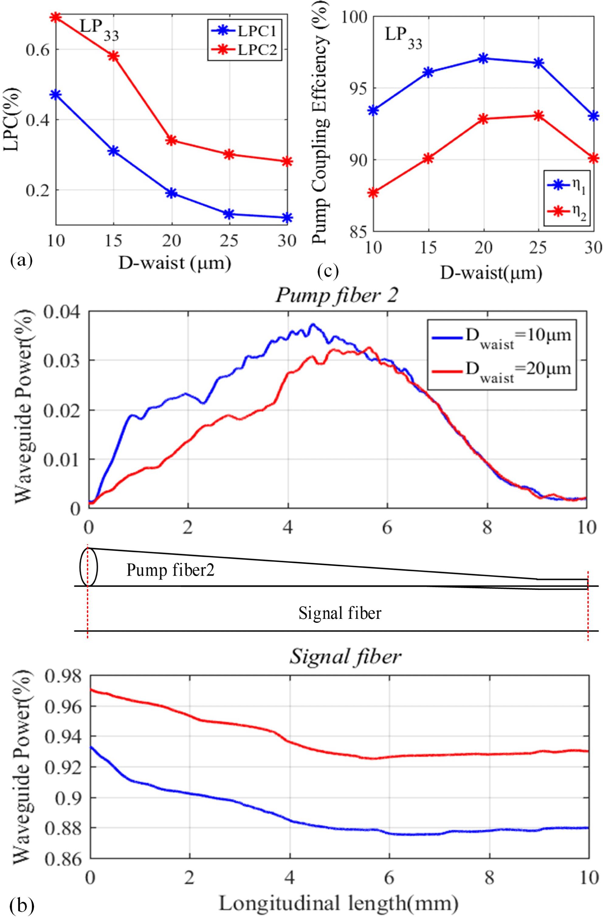
Fig. 2. (a)
 ,
,
 with respect to
 of Stage 1. (b) The evolution of waveguide power in Pump fiber 2 and signal fiber (inner cladding) to the total pump power along the length of Pump fiber 2 of Stage 2 for
 and
and
 . (c) LPC1, LPC2 with respect to
 of Stage 1 (LP
 launching at Stage 1,
 ,
,
 of Stage 2 is
 ).
).
,
with respect to
of Stage 1. (b) The evolution of waveguide power in Pump fiber 2 and signal fiber (inner cladding) to the total pump power along the length of Pump fiber 2 of Stage 2 for
and
. (c) LPC1, LPC2 with respect to
of Stage 1 (LP
launching at Stage 1,
,
of Stage 2 is
). Fig. 3. (a)
 and LPC with respect to
 of Stage 2. (b) The evolution of waveguide power in Pump fiber 2 and signal fiber (inner cladding) to the total pump power along the length of Pump fiber 2 of Stage 2 for different
 of Stage 2. (LP33 launching at Stage 1,
 (at both stages) is
 .)
.)
and LPC with respect to
of Stage 2. (b) The evolution of waveguide power in Pump fiber 2 and signal fiber (inner cladding) to the total pump power along the length of Pump fiber 2 of Stage 2 for different
of Stage 2. (LP33 launching at Stage 1,
(at both stages) is
.) Fig. 4. The schematic of the combiner fabrication system.
Fig. 5. Diameter scanning of pump fiber tapers at different longitudinal positions for (a) Samples 1–4 (around the taper waist) and (b) Sample 5.
Fig. 6. The experimental setup of pump coupling efficiency testing system and the microscope image of the combiner (with LD pumping).
Fig. 7. The results of pump coupling efficiency testing for Samples 1–4 as Stage 1. (a) Only with LD1 pumping; (b) with LD1 and LD2 pumping together.
Fig. 8. The highest temperature along the fiber coating of Stage 2 for Samples 1–3 as Stage 1: (a) only LD1 injecting pump power or (b) LD1 together with LD2 injecting pump power (the blue square stands for the case that only LD2 injected).
Fig. 9. The thermal images of the cascaded combiner when injecting 186.3 W pump light of LD1 and 215.5 W pump light of LD2. (a) Sample 3 as Stage 1; (b) Sample 1 as Stage 1.
Fig. 10. (a) Experimental setup of the component test with 1018 nm fiber laser pumping. (b) The thermal image of the cascaded combiner when injecting total 1018 nm laser light of 1088 W (545 W for Stage 1 and 543 W for Stage 2). Stage 1/Stage 2: Sample 3/Sample 5.
|
Table 1.  and pump coupling efficiency of the combiner samples.
and pump coupling efficiency of the combiner samples. 

Set citation alerts for the article
Please enter your email address

© Copyright 2018-2021 | Chinese Laser Press. All Rights Reserved 沪ICP备15018463号-20