
Chengmin Lei, Zilun Chen, Yanran Gu, Hu Xiao, Jing Hou, "Loss mechanism of all-fiber cascaded side pumping combiner," High Power Laser Sci. Eng. 6, 04000e56 (2018)
- High Power Laser Science and Engineering
- Vol. 6, Issue 4, 04000e56 (2018)
Abstract
1 Introduction
Fiber lasers have seen progressive development and been widely applied in industrial field, defense technology and medical science over the past several decades. The investigation of all-fiber components for the highly integrated high power fiber laser and amplifier systems has been increased in recent years. One of the most key components is a pump/signal combiner. The side pumping combiner, in which the pump light is coupled into the double-clad fiber through the fiber side, is of great interest in these two decades. The attractive characteristics of side pumping combiner, such as uninterrupted signal fiber core and unlimited pump points, which an end pumping combiner (such as tapered-fused bundle (TFB) technique
[
In order to further increase the output power from the fiber laser, higher pumping power coupled into double-clad signal fiber is required. Since the pumping points in a side pumping scheme are not limited, multi-point or cascaded side pumping can be realized. Tan
 structure (
 can be 7 or more) with high coupling efficiency for every pump fiber
[
can be 7 or more) with high coupling efficiency for every pump fiber
[
 structure is more advisable for high pump coupling efficiency requirement, while using cascaded scheme by inserting more pump fibers at several positions along the signal fiber will also reduce the coupling efficiency and insert more signal loss and beam quality degradation
[
structure is more advisable for high pump coupling efficiency requirement, while using cascaded scheme by inserting more pump fibers at several positions along the signal fiber will also reduce the coupling efficiency and insert more signal loss and beam quality degradation
[
In this paper, we report simulations and experiments about the pump power loss mechanism of two-cascaded side pumping combiner based on tapered-fused technique for the first time. First, the optical design and numerical modeling of two-cascaded combiner are depicted. Then, simulation results for different parameters of the two combiners are shown in Section
 combiners with different parameters is demonstrated. Last, a cascaded component is used for handling a pump power of 1088 W when employing 1018 nm fiber laser as the pump source, with total pump coupling efficiency of 96.4%.
Sign up for High Power Laser Science and Engineering TOC. Get the latest issue of High Power Laser Science and Engineering delivered right to you!Sign up now
2 Theoretical analysis
2.1 Numerical model
The numerical simulation is carried out by beam propagation method (BPM), which is a method for solving the Helmholtz equation for optical fibers
[
 side pumping combiners. The core/cladding diameter of the double-clad signal fiber is 20 and
 , respectively, with a cladding numerical aperture (NA) of 0.46. The core/cladding diameter of two pump fibers is
 with
with
 .
.
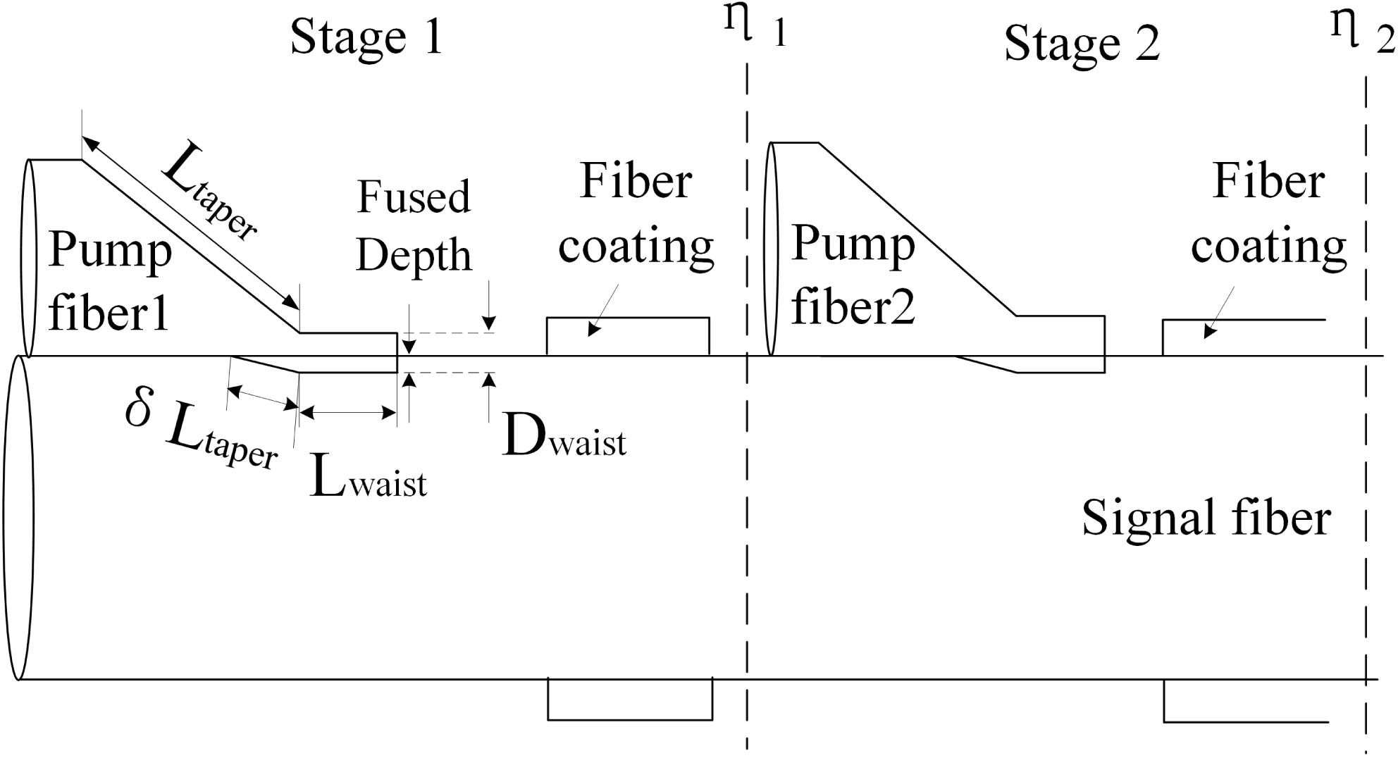
 and
and
 are the lengths of the transition region and the taper waist. The diameter of the taper waist is defined as
 . As for the geometrical shape of the taper in the longitudinal direction, for simplicity, a linear shape is assumed in the simulations instead of the parabolic shape. Since the simulation of side pumping combiner with the consideration of fused depth may be more reliable as discussed in our previous work
[
. As for the geometrical shape of the taper in the longitudinal direction, for simplicity, a linear shape is assumed in the simulations instead of the parabolic shape. Since the simulation of side pumping combiner with the consideration of fused depth may be more reliable as discussed in our previous work
[
 and reaches the maximum at the taper waist (this maximum depth is defined as fused depth in the calculation). The distance between the coating edge and the taper waist end of the pump fiber is assumed to be 5 mm and the coating length for every combiner to be 5 mm. Fused depth for both stages is
 . Detailed information about the parameter setting and numerical model description of noncascaded side pumping combiner can be found in Ref. [
The analysis of the loss mechanism for a noncascaded side pumping combiner by tapered-fused method has been proposed and well-discussed recently. The simulations about the influence of taper ratio, taper length, pump light input NA and number of pump ports on the pump efficiency and loss mechanism were performed by using the ray tracing method in Ref. [
 ) and Stage 2 (
 ), LPC for Stage 1 and for Stage 2 as well as the power loss along the coupling region of Stage 2, under the condition of launching pump light from Pump fiber 1. More specifically,
 and
and
 refer to the integral power over the waveguide cross section at the longitudinal position of the end of coating at Stages 1 and 2. In the simulation work of Ref. [
2.2 Power loss analysis in Stage 2
Figure
 of Stage 1 on the pump coupling efficiency
 and
and
 from Stage 1. Since the pump fiber is a multi-mode fiber, we randomly select a higher-mode LP
 as the launch field of the simulation. At a constant
 , a decrease of coupling efficiency can be seen after the propagation of Stage 2, as shown in Figure
 ,
,
 of 96.84% is obtained while the coupling efficiency after Stage 2 is calculated to be 92.48%. This can be explained by two types of power loss, one of which is power loss along the coupling region of Stage 2. As shown in Figure
 is
is
 and
and
 . The longitudinal length of 0 mm in Figure
Another type of power loss arises from LPC at the signal fiber coating of Stage 2. Figure
 of Stage 1. In general, it can be seen that LPC2 is relatively higher than LPC1, under the same
 of Stage 1 (or the same structure parameter of the component). In Stage 1, for the pump light coupling into the signal fiber successfully, as we analyzed before
[
of Stage 1 (or the same structure parameter of the component). In Stage 1, for the pump light coupling into the signal fiber successfully, as we analyzed before
[
It is also found that
 of Stage 1 will influence the mentioned two types of loss. For example, as shown in Figure
 of
of
 leads to the power decrease in signal fiber of 5.3% from 93.4% to 88.1%, whereas for
 of
of
 , the power decrease of 4.0% is calculated along the coupling region. As for LPC2, a
 of
of
 leads to LPC2 of 0.69% while for
 of
of
 , only 0.29% of this power is calculated. A lower
 of Stage 1, namely a higher taper ratio (the diameter of the cladding of pump fiber/
 ), will cause further increase of the pump light NA, thus leading to the growth of two types of loss when the light propagates to Stage 2. Therefore, in a two-cascaded structure, a large
 of Stage 1 is desirable, for the purpose of cutting down the loss of pump power (launched from Stage 1) along the coupling region of Stage 2, at the same time reducing LPC at Stage 2 to avoid component damage during high power operation. Even so, a large
 is also inadvisable due to the relatively lower coupling efficiency even at the first stage. Therefore,
 must be carefully selected to satisfy the requirement of a cascaded component for both high pump coupling efficiency and high stability under high power level.
Next, we figure out how the structure parameter of Stage 2 influences the loss mechanism in the two-cascaded side pumping combiner. As discussed before, the pump light inserted from Stage 1 will experience an increase of NA when propagating through the coupling region of Stage 2, thus introducing power loss along the coupling region as well as evident LPC2, which means the waveguide shape at the coupling region of Stage 2 can also influence the loss mechanism in Stage 2. In contrast with fused depth and
 of Stage 2, fused ratio
 is the structure parameter that more significantly influences the coupling coefficient between Pump fiber 2 and the signal fiber. As illustrated in Section
 and reaches the maximum at the taper waist, which means
 is the structure parameter that can describe not only the longitudinal position of fused depth but also the size and extent of the fused region between the pump fiber and signal fiber. Thus, we mainly discuss the impact of
 at Stage 2 on the loss mechanism, keeping the structure parameters of Stage 1 unchanged. Figure
 and LPC2 at different
 of Stage 2 with LP
 launching at Stage 1 and
 at both stages to be
 . As shown in Figures
 launching at Stage 1 and
 at Stage being
 ,
,
 and LPC1 are calculated to be 97.1% and 0.18%. In Figure
 is increased with the rise of
 . For example,
 leads to a
 of 92.5% while for
 ,
,
 of 93.1% is calculated. One reason is the decreased power loss along the coupling region of Stage 2, from 4.5% (97.1%–92.6%) at
 to 3.9% (97.1%–93.2%) at
 , as shown in Figure
 mainly influences the light propagation in the coupling region with fused depth introduced – for example, longitudinal length
 6.3 mm for
 (
(
 –
–
 ), rather than the beginning of the coupling region. Another reason for the growth of
 with
with
 from 0.1 to 0.3 can be the decreased LPC2 to the total pump power from 0.67% to 0.47%, as shown in Figure
2.3 Discussion and conclusion
The simulation implies that first of all, the power loss coupling into the coating in Stage 2 is more serious than that in Stage 1, due to the enhanced LPC derived from light power launching in Stage 1, in conjunction with its own LPC when launching pump power in Stage 2. In the application of a cascaded side pumping combiner, it will take more effort and attention to handle the heat load on the signal fiber coating of the second stage rather than the first one, by improving the packaging design and cooling system of the component. Second, since
 of the first stage strongly influences the loss mechanism of the component as analyzed, it must be carefully selected in the fabrication for the purpose of designing a component with high coupling efficiency as well as low thermal load on the fiber coating. Third, the increase of
 in Stage 2 is an effective approach to improve the coupling efficiency
 and suppress LPC2. During the fusion splicing of the component fabrication,
 can be controllable by the size and scanning region of the heating torch, which means a torch with proper size is required and a scanning program of the torch is recommended to guarantee a sufficient fused region.
3 Experimental results and discussion
3.1 Experimental setup
The heat source for tapering and fusion splicing is a hydrogen–oxygen flame. The fabrication and online testing system, as well as the fabrication process of the combiner was described in our previous work in detail
[
 and scan length of 1 mm during the 50 s fusion time.
Experimentally, we fabricate five
 side pumping combiners with different
 of the tapered pump fiber but the same tapering length and same heating torch parameter setting. By splicing two of these combiner samples, a two-stage-cascaded side pumping combiner is developed. Table
 and pump coupling efficiency of the combiner samples. For the aim of experimentally investigating the influence of
 for the first stage on the performance of the component, Samples 1–4 are used as Stage 1 while Sample 5 is for Stage 2. Figure
 ,
,
 ,
,
 and
and
 , respectively. Slight fluctuations of the diameter, as shown in Figure
 . The lengths of the transition region and the taper waist are 9 mm and 10 mm, respectively, which are identical to that in simulations.
| Sample | Pump coupling efficiency (%) | Stage | |
|---|---|---|---|
| 1 | 23 | 97.1 | 1 |
| 2 | 25 | 98.1 | 1 |
| 3 | 27 | 97.6 | 1 |
| 4 | 30 | 91.6 | 1 |
| 5 | 25 | 98.0 | 2 |
Table 1.  and pump coupling efficiency of the combiner samples.
The experimental setup of pump coupling efficiency testing system for the cascaded side pumping combiner and the microscope images of the combiner is shown in Figure
 with an NA of 0.22. They are spliced to the input pump ports of Stage 1 and Stage 2. The combiner at every stage is fixed on a silica base plate by low-index ultraviolet glue. The silica base plate is set in a component housing which is fixed on a heat sink device (maintaining a constant temperature of
 by water cooling). The working temperature of the fiber coating of every stage can be monitored by thermal imager.
3.2 Experimental results
Figure
 in the simulation). A coupling efficiency of 86.5% is obtained for Sample 3 as Stage 1, which is much higher than that for Samples 1 and 2 as Stage 1. This can be explained by the fact that a larger
 of Stage 1 can lead to a higher
 as analyzed in Section
 of
of
 as Stage 1, the value of
 is only 68.7%, which is due to lower coupling efficiency at Stage 1 before Stage 2 involved (as shown in Table
 according to their own coupling efficiency, under the condition without the consideration of the extra loss mechanism of a cascaded structure as analyzed in Section
Figure
 ,
,
 and
and
 for Samples 1–3 as Stage 1, respectively. This indicates that, in a two-stage-cascaded combiner, samples with different
 as Stage 1 show different thermal load on the fiber coating of Stage 2. A smaller
 of Stage 1 leads to worse coating thermal load, which agrees well with the numerical results shown in Figure
 , the cascaded structure brings extremely serious thermal load on fiber coating of Stage 2, which will limit the power handling capability of the component.
Figures
 whereas it is as high as
 in Stage 2. It can also be observed that the heat load decreases and spreads out gradually along the fiber coating that is packaged in the component housing. This is because the fiber coating is in contact with the silica base plate and a portion of coating loss can be spread by heat sink device. As for the following fiber coating that is not packaged in the combiner housing, the average temperature is tested to be
 . Under higher power level, the heat load of this part cannot be ignored because it is naked in the air with no extra cooling management. Figure
 of Sample 1 as Stage 1.
It should be noted that the pump coupling efficiency and heat load on the fiber coating were proved to be significantly influenced by the pump light input NA numerically and experimentally
[
 side pumping combiner numerically and experimentally for high power fiber lasers
[
side pumping combiner numerically and experimentally for high power fiber lasers
[
 ,
,
 ) by a
 combiner. Sample 3 and Sample 5 act as Stage 1 and Stage 2 in the cascaded scheme. Figure
 , which means the combiner shows an excellent power handling capability in a one-stage structure. However, the highest temperature along the coating of Stage 2 is
 , even though this performance is much better compared with LD as pump source shown in Figure
3.3 Discussion
The experiments reveal that first, the total coupling efficiency of a two-cascaded side pumping combiner is lower than expected, due to the power loss along the coupling region of the latter stage as well as the enhanced LPC in the latter stage, derived from light power launching in Stage 1. Second, the heat load in Stage 2 is more serious than that in Stage 1 even only with pump light injecting to Stage 1, which is the critical limit of the power handling capability for the cascaded structure. Moreover, one should take more effort to handle the heat load on the signal fiber coating of the latter stage rather than the former one. Third, a larger
 of the tapered pump fiber in the former stage is advantageous to reduce the thermal load on the signal fiber coating of the latter stage while only under the condition that the coupling efficiency of the former stage is not decreased due to the variation of
 . The experiments also prove that with the option of using fiber laser as the pump light source, the future opportunities for further improving the performance of a cascaded side pumping combiner, including the total coupling efficiency and the pump power handling capability, appear very bright. A three-stage-cascaded side pumping combiner is also feasible as long as the tapering structure (the taper length and taper waist diameter) and fusion splicing parameter (heating torch size, heating region size, heating temperature) can be well designed through numerical calculation. Even so, our work indicates that the extra pump power loss due to the cascaded scheme cannot be ignored and will cause the decrease of total pump coupling efficiency. Thus, the number of stage is limited by the expected total pump coupling efficiency from users. To further explore the advantage of unlimited pump points for side pumping combiners, a multi-point distributed pumping scheme is also of great potential where the pump fibers are fusion-spliced on the surface of the active fiber directly. In this scheme, the pump power coupled from the former stage of the combiner will be absorbed by the rare-doped signal fiber core and only a portion of the unabsorbed pump light propagates to the coupling region of the next stage, which means the extra pump power loss due to the cascaded structure will significantly decrease. Meanwhile, the inhomogeneous gain distribution and thermal effects occurring at the end of the fiber can also be solved by this scheme.
4 Conclusion
In conclusion, we have investigated the loss mechanism of a two-stage-cascaded side pumping combiner numerically and experimentally. The theoretical analysis indicates that the coupling efficiency is lower than the expected due to the extra power loss when the pump light from the first stage propagates to the next stage, and the LPC on the coating of the second stage is more serious than that in the first stage. Experimentally we fabricate combiners consisting of one pump fiber (
 ,
,
 ) and a signal fiber (
 ,
,
 ) and splice two of them to construct a cascaded scheme. The influences of
 of the tapered pump fiber in the first stage on the thermal load and coupling efficiency of the components are monitored and analyzed. The experiments show good agreement with the BPM simulations. Furthermore, 1018 nm Yb-doped fiber lasers are also adopted to be the pump sources of the combiner. The maximum power handling of 1088 W with a pump coupling efficiency of 96.4% is achieved for a two-cascaded combiner, which shows its advantage in further improving the power handling capacity of a cascaded structure.
References
[1] D. J. Digiovanni, A. J. Stentz.
[2] T. Weber, W. Lüthy, H. P. Weber. Appl. Phys. B, 63, 131(1996).
[3] L. Goldberg, B. Cole, E. Snitzer. Electron. Lett., 33, 2127(1997).
[4] J. P. Koplow, S. W. Moore, D. A. V. Kliner. IEEE J. Quantum Electron., 39, 529(2003).
[5] S. L. Lin, Y. W. Lee, K. Y. Hsu, C. W. Huang. Lasers and Electro-Optics Pacific Rim(2013).
[6] C. W. Huang, D. W. Huang, C. L. Chang, D. Y. Jheng, K. Y. Hsu, C. H. Kuan, S. L. Huang. CLEO: 2011 – Laser Science to Photonic Applications(2011).
[7] T. Theeg, H. Sayinc, J. Neumann, L. Overmeyer, D. Kracht. Opt. Express., 20, 28125(2012).
[8] X. Chen, Q. R. Xiao, G. Y. Jin, P. Yan, M. L. Gong. Chin. Phys. B, 24, 064208(2015).
[9] Q. R. Xiao, P. Yan, H. C. Ren, X. Chen, M. L. Gong. J. Lightwave Technol., 31, 2715(2013).
[10] C. Lei, Z. Chen, J. Leng, Y. Gu, J. Hou. J. Lightwave Technol., 35, 1922(2017).
[11] Q. Xiao, X. Chen, H. Ren, P. Yan, M. Gong. Opt. Lett., 38, 1170(2013).
[12] Q. Tan, T. Ge, X. Zhang, Z. Wang. Laser Phys., 26, 25102(2016).
[13] J. Zheng, W. Zhao, B. Zhao, Z. Li, C. Chang, G. Li, Q. Gao, P. Ju, W. Gao, S. She, P. Wu, C. Hou, W. Li. Opt. Eng., 57, 36105(2018).
[14] S. Zou, H. Chen, H. Yu, J. Sun, P. Zhao, X. Lin. Appl. Phys. B, 123, 288(2017).
[15] Q. Xiao, P. Yan, H. Ren, X. Chen, M. Gong. Appl. Opt., 52, 409(2013).
[16] M. D. Feit, J. A. Fleck. Appl. Opt., 17, 3990(1978).
[17] Y. Gu, C. Lei, J. Liu, R. Li, L. Liu, H. Xiao. Opt. Eng., 56, 11619(2017).


Set citation alerts for the article
Please enter your email address

© Copyright 2018-2021 | Chinese Laser Press. All Rights Reserved 沪ICP备15018463号-20